Test D: Instrument Cluster Does Not Respond To NGS Tester
- Turn ignition switch to LOCK position. Disconnect instrument cluster 20-pin harness connector C220b. Inspect harness connector for loose, damaged or corroded terminals. If problem exists, repair harness connector as necessary and retest system for normal operation. If problem does not exist, go to next step.
- Connect instrument cluster harness connector C220b and connect NGS tester. Turn ignition switch to RUN position. Perform data link diagnostic test. See DATA LINK DIAGNOSTIC TEST
under SELF-DIAGNOSTIC SYSTEM. If NGS tester indicates ICM: NO RESPONSE ON CKT 914 (BUS +), go to next step. If NGS tester indicates ICM: NO RESPONSE ON CKT 915 (BUS -), go to step 6
.
- Turn ignition switch to LOCK position. Disconnect NGS tester. Disconnect instrument cluster harness connector C220b. Measure resistance between terminal No. 15 (Gray/Violet wire) at instrument cluster harness connector C220b and terminal No. 2 (Gray/Red wire) at Data Link Connector (DLC). See Figure
and Fig 1
. If resistance is greater than 5 ohms, go to next step. If resistance is 5 ohms or less, replace instrument cluster and retest system for normal operation.
- Disconnect joint connector No. 4 harness connector C223, located behind left side of instrument panel. Measure resistance in Gray/Violet wire between terminal No. 13 at joint connector No. 4 harness connector C223 and terminal No. 15 at instrument cluster harness connector C220b. See Figure
and Fig 1
. If resistance is 5 ohms or less, go to next step. If resistance is greater than 5 ohms, repair open in Gray/Violet wire between joint connector No. 4 and instrument cluster. Retest system for normal operation.
- Measure resistance between terminals No. 13 and 14 at joint connector No. 4 (component side). See Figure
. If resistance is 5 ohms or less, repair open in Gray/Red wire between joint connector No. 4 and DLC. Retest system for normal operation. If resistance is greater than 5 ohms, replace joint connector No. 4 and retest system for normal operation.
- Turn ignition switch to LOCK position. Disconnect NGS tester. Disconnect instrument cluster harness connector C220b. Measure resistance between terminal No. 16 (Blue/White wire) at instrument cluster harness connector C220b and terminal No. 10 (Blue/Red wire) at Data Link Connector (DLC). See Figure
and Fig 1
. If resistance is 5 ohms or less, replace instrument cluster and retest system for normal operation. If resistance is greater than 5 ohms, go to next step.
- Disconnect joint connector No. 4 harness connector C223, located behind left side of instrument panel. Measure resistance in Blue/White wire between terminal No. 10 at joint connector No. 4 harness connector C223 and terminal No. 16 at instrument cluster harness connector C220b. See Figure
and Fig 1
. If resistance is 5 ohms or less, go to next step. If resistance is greater than 5 ohms, repair open in Blue/White wire between joint connector No. 4 and instrument cluster. Retest system for normal operation.
- Measure resistance between terminals No. 9 and 10 at joint connector No. 4 (component side). See Figure
. If resistance is 5 ohms or less, repair open in Blue/Red wire between joint connector No. 4 and DLC. Retest system for normal operation. If resistance is greater than 5 ohms, replace joint connector No. 4 and retest system for normal operation.
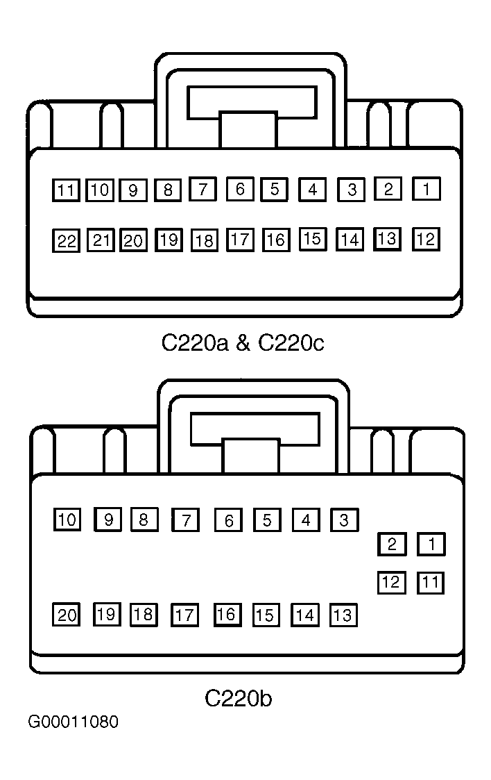 Courtesy of FORD MOTOR CO.