Test A: Fuel Sender Circuit Failure (DTC B1201); Fuel Sender Short To Ground (DTC B1204)
- Connect NGS tester to Data Link Connector (DLC). Turn ignition switch to RUN position. Select and trigger instrument cluster active command FUELLEVEL. Adjust scroll knob to read 50 percent. Fuel gauge reading should be at half tank. Adjust scroll knob to read 100 percent. Fuel gauge reading should be full. If fuel gauge responded as specified, go to next step. If fuel gauge did not respond as specified, replace instrument cluster.
- Turn ignition switch to OFF position. Disconnect fuel tank sender harness connector C415. Connect one lead of Instrument Gauge System Tester (014-R1063) to terminal No. 8 (Yellow/White wire) at fuel tank sender harness connector C415. Connect the other lead of tester to terminal No. 5 (Orange/Yellow wire) at fuel tank sender harness connector C415. See Fig 1
. Set tester to 15 ohms. Turn ignition switch to RUN position. Turn ignition switch to OFF position. Turn ignition switch to RUN position and wait one minute. If fuel gauge reads empty or below, go to next step. If fuel gauge does not read empty or below, go to step 5
.
- Turn ignition switch to OFF position. Set tester to 160 ohms. Turn ignition switch to RUN position and wait one minute. Fuel gauge should started at empty and go to full or above. If fuel gauge did not respond as specified, go to next step. If fuel gauge responded as specified, replace fuel tank sender.
- Inspect fuel tank. If fuel tank is okay, repair or replace fuel sender assembly as necessary. If fuel tank is damaged, repair or replace fuel tank as necessary.
- Turn ignition switch to OFF position. Disconnect instrument cluster harness connector C256. Measure resistance between ground and terminal No. 4 (Yellow/White wire) at instrument cluster harness connector C256. Resistance should be greater than 10 k/ohms. Measure resistance in Yellow/White wire between terminal No. 4 at instrument cluster harness connector C256 and terminal No. 8 at fuel tank sender harness connector. See Fig 1
and Fig 2
. Resistance should be 5 ohms or less. If resistance is as specified, go to next step. If resistance is not as specified, repair short or open in Yellow/White wire.
- Disconnect instrument cluster harness connector C255. Measure resistance between ground and terminal No. 28 (Orange/Yellow wire) at instrument cluster harness connector C255. Resistance should be greater than 10 k/ohms. Measure resistance in Orange/Yellow wire between terminal No. 28 at instrument cluster harness connector C255 and terminal No. 5 at fuel tank sender harness connector. Resistance should be 5 ohms or less. If resistance is as specified, replace instrument cluster. If resistance is not as specified, repair short or open in Orange/Yellow wire.
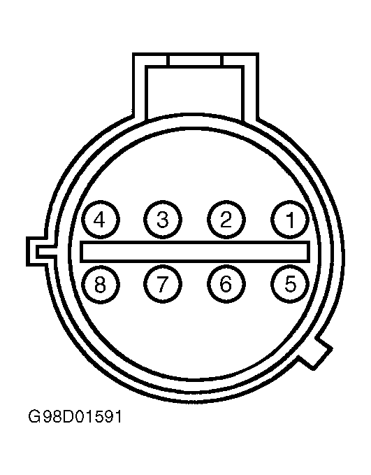 Courtesy of FORD MOTOR CO.
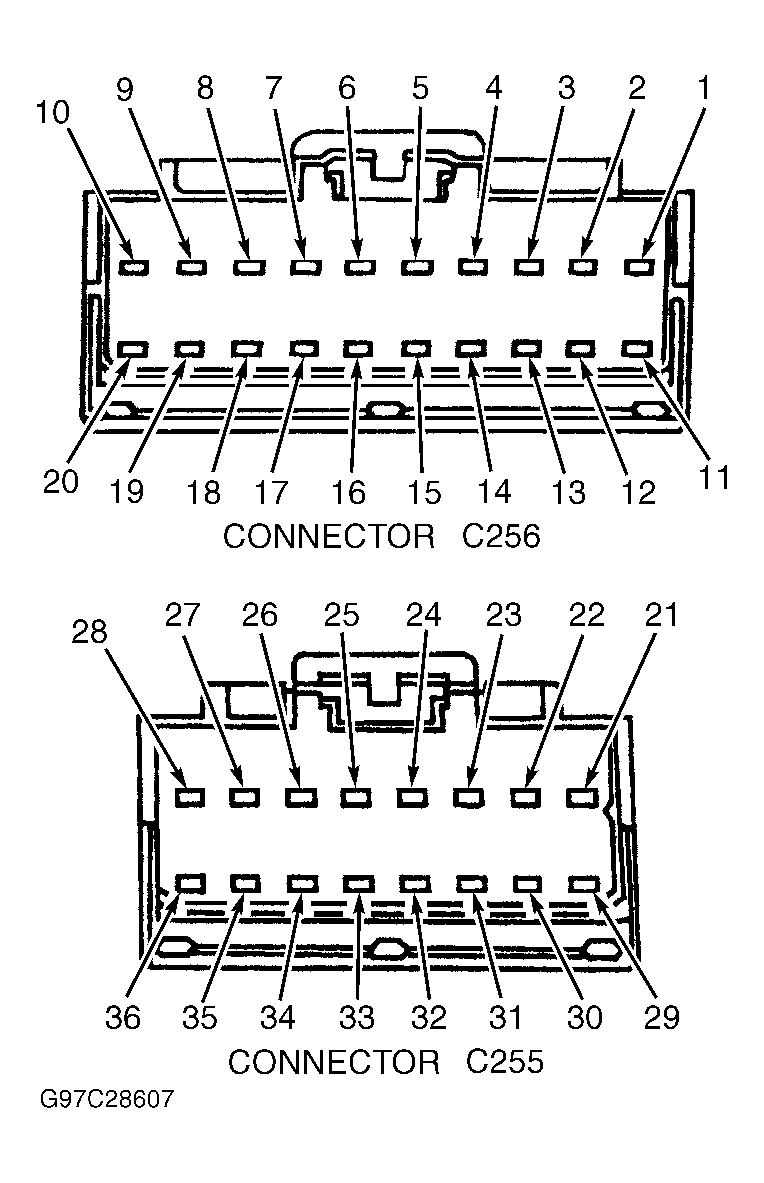 Courtesy of FORD MOTOR CO.