Test A: No Communication With Gem Module
- Ensure ignition is off. Connect NGS tester to Data Link Connector (DLC). Using NGS tester, read IGN_GEM PID while rotating ignition switch through START, RUN, OFF and ACC positions. If PID values agree with ignition switch positions, go to next step. If PID values do not agree with ignition switch positions, repair open circuit between ignition switch and instrument panel fuse block. See appropriate POWER DISTRIBUTION wiring diagram in SYSTEM WIRING DIAGRAMS article in the WIRING DIAGRAMS section. Clear DTCs and retest system.
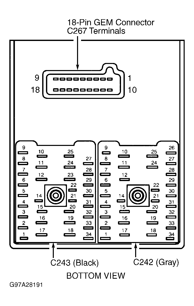
- Disconnect instrument panel fuse/relay block Black connector C243. Measure voltage between ground and connector C243 terminal No. 11 (Tan/Black wire). See Fig 2
. If voltage is more than 10 volts, go to next step. If voltage is less than 10 volts, repair Tan/Black wire. Clear DTCs and retest system.
 Courtesy of FORD MOTOR CO.
- Turn ignition switch to OFF position. Disconnect GEM 18-pin connector C267. Reconnect C243 connector. Turn ignition on. Measure voltage between ground and connector C267 terminal No. 4. See Fig 1
. Measure voltage between ground and connector C267 terminal No. 16. If voltages are more than 10 volts, go to next step. If voltages are less than 10 volts, replace fuse/relay block. Clear DTCs and retest system.
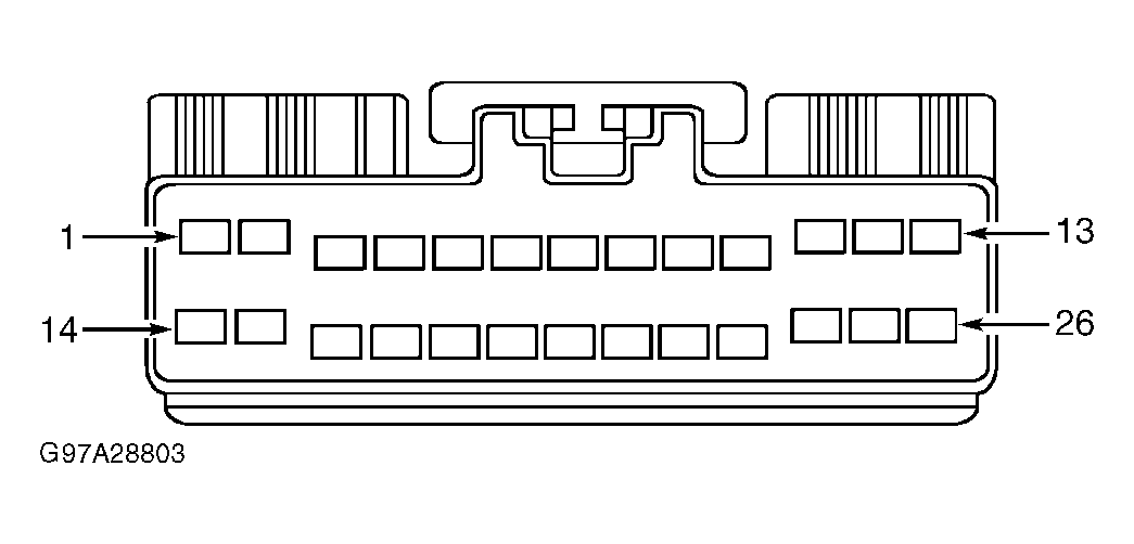
- Turn ignition switch to OFF position. Disconnect Gray GEM 26-pin connector C239. Measure resistance between ground and connector C239 terminal No. 26 (Black/Light Blue wire). See Fig 2
. If resistance is less than 5 ohms, go to next step. If resistance is more than 5 ohms, repair open in Black/Light Blue wire. Clear DTCs and retest system.
 Courtesy of FORD MOTOR CO.
- Measure resistance between ground and connector C239 terminal No. 14 (Black/Light Blue wire). See Fig 2
. If resistance is less than 5 ohms, problem is in Module Communications network. See MODULE COMMUNICATIONS NETWORK article. If resistance is more than 5 ohms, repair open in Black/Light Blue wire. Clear DTCs and retest system.