Transmission Range Indicator Never/Always On
- Press and hold brake pedal. Turn ignition on. Observe instrument cluster transmission range indicator. Move transmission selector lever through all gear ranges. If instrument cluster transmission range indicator illuminates with each gear range selector lever position, go to step 3). If instrument cluster transmission range indicator does not illuminate with each gear range selector lever position, go to next step.
- Turn ignition off. Connect NGS tester to Data Link Connector (DLC). Retrieve HEIC continuous and self-test DTCs. If DTC U1059 is present, see HYBRID ELECTRONIC INSTRUMENT CLUSTER (HEIC) MODULE DTC DEFINITIONS table under SELF-DIAGNOSTIC SYSTEM to continue diagnosis. If DTC U1059 is not present, repair HEIC and retest system.
- Observe console transmission range indicator. Move transmission selector lever through all gear ranges. If console transmission range indicator illuminates with any gear range selector lever position, go to step 5). If console transmission range indicator does not illuminate with any gear range selector lever position, go to next step.
- Turn ignition off. Disconnect console transmission range indicator connector C319. See Fig 1
. Turn ignition on. Measure voltage between ground and console transmission range indicator connector C319 terminal No. 13 (Purple/Orange wire). If battery voltage is present, replace console transmission range indicator and retest system. If battery voltage is not present, repair open in Purple/Orange wire between fuse No. 28 and indicator connector C319 and retest system.
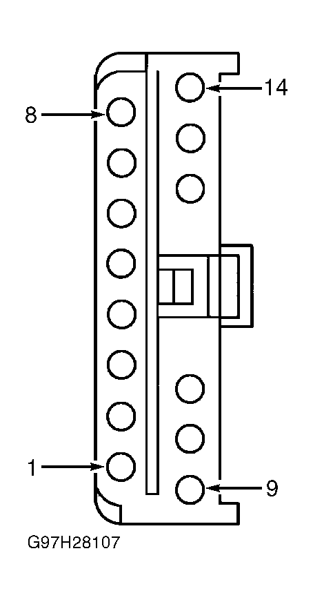 Courtesy of FORD MOTOR CO.
- Turn ignition off and back on. Place transmission gear range selector lever in Park. If console transmission range "P" indicator is on, go to step 14). If console transmission range "P" indicator is not on, go to next step.
- Turn ignition off. Connect NGS tester to Data Link Connector (DLC). Using NGS tester, select HEIC active command INSTRUMENT PANEL LAMP CONTROL. Select PRNDL LMP. Select PARK, then trigger ON. If console transmission range "P" indicator is on, go to next step. If console transmission range "P" indicator is not on, go to step 12).
- Turn ignition off. Remove instrument cluster. See INSTRUMENT CLUSTER
under REMOVAL & INSTALLATION. Disconnect HEIC connector C294. See Figure
. Turn ignition on. Measure voltage between ground and HEIC connector C294 terminal No. 1 (Orange/White wire). If battery voltage is present, go to step 10). If battery voltage is not present, go to next step.
- Turn ignition off. Disconnect console transmission range indicator connector C319. See Fig 1
. Measure resistance between ground and HEIC connector C294 terminal No. 1 (Orange/White wire). If resistance is 10 k/ohms or less, repair short to ground in Orange/White wire and retest system. If resistance is more than 10 k/ohms, go to next step.
- Measure resistance of Orange/White wire between HEIC connector C294 terminal No. 1 and console transmission range indicator connector C319 terminal No. 14. If resistance is 5 ohms or less, replace console transmission range indicator and retest system. If resistance is more than 5 ohms, repair open in Orange/White wire and retest system.
- Measure voltage between ground and HEIC connector C294 terminal No. 1 (Orange/White wire). If battery voltage is present, go to next step. If battery voltage is not present, repair HEIC and retest system.
- Turn ignition off. Disconnect console transmission range indicator connector C319. See Fig 1
. Turn ignition on. Measure voltage between ground and HEIC connector C294 terminal No. 1 (Orange/White wire). If battery voltage is present, repair short to B+ in Orange/White wire and retest system. If battery voltage is not present, replace console transmission range indicator and retest system.
- Turn ignition off. Disconnect HEIC connector C294. See Figure
. Turn ignition on. Connect jumper wire between ground and HEIC c connector C294 terminal No. 10 (Pink/Orange wire). If "P" indicator on console illuminates, repair HEIC and retest system. If "P" indicator on console does not illuminate, go to next step.
- Turn ignition off. Disconnect console transmission range indicator connector C319. See Fig 1
. Measure resistance of Pink/Orange wire between HEIC connector C294 terminal No. 10 and console transmission range indicator connector C319 terminal No. 1. If resistance is 5 ohms or less, replace console transmission range indicator and retest system. If resistance is more than 5 ohms, repair open in Pink/Orange wire between HEIC connector and console transmission range indicator connector and retest system.
- Place transmission in Reverse. Turn ignition on. If console transmission range indicator "R" is illuminated, go to step 17). If console transmission range indicator "R" is not illuminated, go to next step.
- Turn ignition off. Disconnect console transmission range indicator connector C319. See Fig 1
. Connect NGS tester to Data Link Connector (DLC). Turn ignition on. Using NGS tester, select HEIC active command INSTRUMENT PANEL LAMP CONTROL. Select PRNDL LMP. Select REV, then trigger ON. Measure resistance between ground and console transmission range indicator connector C319 terminal No. 2 (Yellow/Light Blue wire). If resistance is 5 ohms or less, replace console transmission range indicator and retest system. If resistance is more than 5 ohms, go to next step.
- Turn ignition off. Disconnect HEIC connector C294. See Figure
. Measure resistance of Yellow/Light Blue wire between HEIC connector C294 terminal No. 9 and console transmission range indicator connector C319 terminal No. 2. If resistance is 5 ohms or less, repair HEIC and retest system. If resistance is more than 5 ohms, repair open in Yellow/Light Blue wire and retest system.
- Place transmission in Neutral. Press and hold brake pedal. Turn ignition on. If console transmission range indicator "N" is illuminated, go to step 20). If console transmission range indicator "N" is not illuminated, go to next step.
- Turn ignition off. Disconnect console transmission range indicator connector C319. See Fig 1
. Connect NGS tester to Data Link Connector (DLC). Turn ignition on. Using NGS tester, select HEIC active command INSTRUMENT PANEL LAMP CONTROL. Select PRNDL LMP. Select NEUT, then trigger ON. Measure resistance between ground and console transmission range indicator connector C319 terminal No. 3 (White/Black wire). If resistance is 5 ohms or less, replace console transmission range indicator and retest system. If resistance is more than 5 ohms, go to next step.
- Turn ignition off. Disconnect HEIC connector C294. See Figure
. Measure resistance of White/Black wire between HEIC connector C 294 terminal No. 8 and console transmission range indicator connector C319 terminal No. 3. If resistance is 5 ohms or less, repair HEIC and retest system. If resistance is more than 5 ohms, repair open in White/Black wire and retest system.
- Place transmission in Drive. Press and hold brake pedal. Turn ignition on. If console transmission range indicator "D" is illuminated, go to step 23). If console transmission range indicator "D" is not illuminated, go to next step.
- Turn ignition off. Disconnect console transmission range indicator connector C319. See Fig 1
. Connect NGS tester to Data Link Connector (DLC). Turn ignition on. Using NGS tester, select HEIC active command INSTRUMENT PANEL LAMP CONTROL. Select PRNDL LMP. Select DRV, then trigger ON. Measure resistance between ground and console transmission range indicator connector C319 terminal No. 4 (Gray/White wire). If resistance is 5 ohms or less, replace console transmission range indicator and retest system. If resistance is more than 5 ohms, go to next step.
- Turn ignition off. Disconnect HEIC connector C294. See Figure
. Measure resistance of Gray/White wire between HEIC connector C2 94 terminal No. 7 and console transmission range indicator connector C319 terminal No. 4. If resistance is 5 ohms or less, repair HEIC and retest system. If resistance is more than 5 ohms, repair open in Gray/White wire and retest system.
- Place transmission in Low-2. Press and hold brake pedal. Turn ignition on. If console transmission range indicator "2" is illuminated, go to step 26). If console transmission range indicator "2" is not illuminated, go to next step.
- Turn ignition off. Disconnect console transmission range indicator connector C319. See Fig 1
. Connect NGS tester to Data Link Connector (DLC). Turn ignition on. Using NGS tester, select HEIC active command INSTRUMENT PANEL LAMP CONTROL. Select PRNDL LMP. Select LOW2, then trigger ON. Measure resistance between ground and console transmission range indicator connector C319 terminal No. 5 (Brown/Orange wire). If resistance is 5 ohms or less, replace console transmission range indicator and retest system. If resistance is more than 5 ohms, go to next step.
- Turn ignition off. Disconnect HEIC connector C294. See Figure
. Measure resistance of Brown/Orange wire between HEIC connector C294 terminal No. 2 and console transmission range indicator connector C319 terminal No. 5. If resistance is 5 ohms or less, repair HEIC and retest system. If resistance is more than 5 ohms, repair open in Brown/Orange wire and retest system.
- Place transmission in Low-1. Press and hold brake pedal. Turn ignition on. If console transmission range indicator "1" is illuminated, go to step 29). If console transmission range indicator "1" is not illuminated, go to next step.
- Turn ignition off. Disconnect console transmission range indicator connector C319. See Fig 1
. Connect NGS tester to Data Link Connector (DLC). Turn ignition on. Using NGS tester, select HEIC active command INSTRUMENT PANEL LAMP CONTROL. Select PRNDL LMP. Select LOW1, then trigger ON. Measure resistance between ground and console transmission range indicator connector C319 terminal No. 6 (Pink/Yellow wire). If resistance is 5 ohms or less, replace console transmission range indicator and retest system. If resistance is more than 5 ohms, go to next step.
- Turn ignition off. Disconnect HEIC connector C294. See Figure
. Measure resistance of Pink/Yellow wire between HEIC connector C 294 terminal No. 3 and console transmission range indicator connector C319 terminal No. 6. If resistance is 5 ohms or less, repair HEIC and retest system. If resistance is more than 5 ohms, repair open in Pink/Yellow wire and retest system.
- Place transmission in Park. Turn ignition on. If console transmission range indicator "P" is illuminated, go to next step. If console transmission range indicator "P" is not illuminated, go to step 32).
- Turn ignition off. Disconnect console transmission range indicator connector C319. See Fig 1
. Measure resistance between ground and console transmission range indicator connector C319 terminal No. 1 (Pink/Orange wire). If resistance is 10 k/ohms or less, go to next step. If resistance is more than 10 k/ohms, replace console transmission range indicator and retest system.
- Disconnect HEIC connector C294. Measure resistance between ground and console transmission range indicator connector C319 terminal No. 1 (Pink/Orange wire). If resistance is 10 k/ohms or less, repair short to ground in Pink/Orange wire and retest system. If resistance is more than 10 k/ohms, repair HEIC and retest system.
- Place transmission in Park. Turn ignition on. If console transmission range indicator "R" is illuminated, go to next step. If console transmission range indicator "R" is not illuminated, go to step 35).
- Turn ignition off. Disconnect console transmission range indicator connector C319. See Fig 1
. Measure resistance between ground and console transmission range indicator connector C319 terminal No. 2 (Yellow/Light Blue wire). If resistance is 10 k/ohms or less, go to next step. If resistance is more than 10 k/ohms, replace console transmission range indicator and retest system.
- Disconnect HEIC connector C294. Measure resistance between ground and console transmission range indicator connector C319 terminal No. 2 (Yellow/Light Blue wire). If resistance is 10 k/ohms or less, repair short to ground in Yellow/Light Blue wire and retest system. If resistance is more than 10 k/ohms, repair HEIC and retest system.
- Place transmission in Park. Turn ignition on. If console transmission range indicator "N" is illuminated, go to next step. If console transmission range indicator "N" is not illuminated, go to step 38).
- Turn ignition off. Disconnect console transmission range indicator connector C319. See Fig 1
. Measure resistance between ground and console transmission range indicator connector C319 terminal No. 3 (White/Black wire). If resistance is 10 k/ohms or less, go to next step. If resistance is more than 10 k/ohms, replace console transmission range indicator and retest system.
- Disconnect HEIC connector C294. Measure resistance between ground and console transmission range indicator connector C319 terminal No. 3 (White/Black wire). If resistance is 10 k/ohms or less, repair short to ground in White/Black wire and retest system. If resistance is more than 10 k/ohms, repair HEIC and retest system.
- Place transmission in Park. Turn ignition on. If console transmission range indicator "D" is illuminated, go to next step. If console transmission range indicator "D" is not illuminated, go to step 41).
- Turn ignition off. Disconnect console transmission range indicator connector C319. See Fig 1
. Measure resistance between ground and console transmission range indicator connector C319 terminal No. 4 (Gray/White wire). If resistance is 10 k/ohms or less, go to next step. If resistance is more than 10 k/ohms, replace console transmission range indicator and retest system.
- Disconnect HEIC connector C294. Measure resistance between ground and console transmission range indicator connector C319 terminal No. 4 (Gray/White wire). If resistance is 10 k/ohms or less, repair short to ground in Gray/White wire and retest system. If resistance is more than 10 k/ohms, repair HEIC and retest system.
- Place transmission in Park. Turn ignition on. If console transmission range indicator "2" is illuminated, go to next step. If console transmission range indicator "2" is not illuminated, go to step 44).
- Turn ignition off. Disconnect console transmission range indicator connector C319. See Fig 1
. Measure resistance between ground and console transmission range indicator connector C319 terminal No. 5 (Brown/Orange wire). If resistance is 10 k/ohms or less, go to next step. If resistance is more than 10 k/ohms, replace console transmission range indicator and retest system.
- Disconnect HEIC connector C294. Measure resistance between ground and console transmission range indicator connector C319 terminal No. 5 (Brown/Orange wire). If resistance is 10 k/ohms or less, repair short to ground in Brown/Orange wire and retest system. If resistance is more than 10 k/ohms, repair HEIC and retest system.
- Place transmission in Park. Turn ignition on. If console transmission range indicator "1" is illuminated, go to next step. If console transmission range indicator "1" is not illuminated, HEIC and console transmission range indicator is operating properly. Reverify symptom and retest system.
- Turn ignition off. Disconnect console transmission range indicator connector C319. See Fig 1
. Measure resistance between ground and console transmission range indicator connector C319 terminal No. 6 (Pink/Yellow wire). If resistance is 10 k/ohms or less, go to next step. If resistance is more than 10 k/ohms, replace console transmission range indicator and retest system.
- Disconnect HEIC connector C294. Measure resistance between ground and console transmission range indicator connector C319 terminal No. 6 (Pink/Yellow wire). If resistance is 10 k/ohms or less, repair short to ground in Brown/Orange wire and retest system. If resistance is more than 10 k/ohms, repair HEIC and retest system.