No Communication With Steering Column/Ignition/Lighting (SCIL) Control Module
- Ensure ignition is off. Disconnect Steering
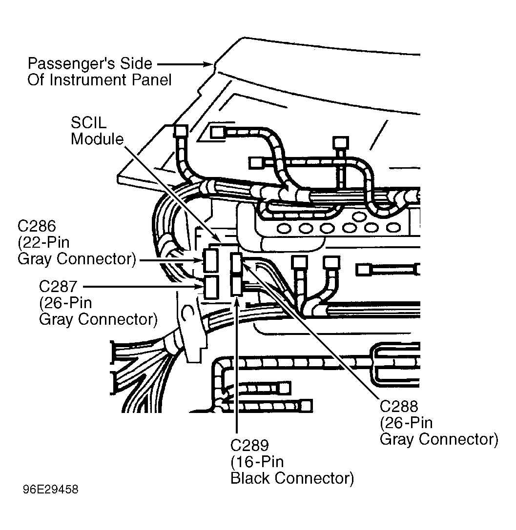
- Column/Ignition/Lighting (SCIL) control module connector C288. SCIL is located behind bottom right side of instrument panel. See Fig 1
and Fig 2
. Measure resistance between ground and SCIL module connector C288 terminal No. 14 (Black/Light Blue wire). If resistance is 5 ohms or less, go to next step. If resistance is more than 5 ohms, repair open in Black/Light Blue wire. Repeat SCIL module self-test.
- Disconnect SCIL module connector C287. See Fig 1
and Fig 2
. Measure resistance between ground and SCIL module connector C287 terminal No. 7 (Black wire). If resistance is 5 ohms or less, go to next step. If resistance is more than 5 ohms, repair open in Black wire. Repeat SCIL module self-test.
- Measure voltage between ground and SCIL module connector C287 terminals No. 11 (Dark Blue/Light Green wire), No. 14 (Red/Orange wire), No. 15 (White/Light Green wire) and No. 26 (Light Blue/Red wire). If battery voltage is present in all tests, go to MODULE COMMUNICATIONS NETWORK article to diagnose network problem. If battery voltage is not present in any test, repair open in appropriate wire and go to next step. See WIRING DIAGRAMS
.
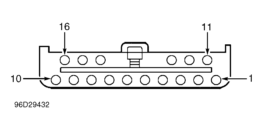
- Disconnect SCIL module connector C289. See Fig 1
and Fig 3
. Measure voltage between ground and SCIL module connector C289 terminals No. 5 (Brown/White wire), No. 6 (Orange/Black wire) and No. 7 (Pink/Light Green wire). If battery voltage is present in all tests, go to MODULE COMMUNICATIONS NETWORK article to diagnose network problem. If battery voltage is not present in any test, repair open in appropriate wire. See WIRING DIAGRAMS
. Repeat SCIL module self-test.
 Courtesy of FORD MOTOR CO.
 Courtesy of FORD MOTOR CO.
 Courtesy of FORD MOTOR CO.