No Communication With Hybrid Electronic Instrument Cluster (HEIC)
- Ensure ignition is off. Remove instrument cluster. See INSTRUMENT CLUSTER
under REMOVAL & INSTALLATION. Disconnect HEIC connector C294. See Fig 1
. Measure voltage between ground and HEIC connector C294 terminal No. 6 (Red wire). If battery voltage is present, go to step 5). If battery voltage is not present, go to next step.
- Remove and inspect fuse No. 20 (10-amp) located in instrument panel fuse panel. If fuse is okay, repair open in Red wire between fuse and HEIC connector C294 and retest system. If fuse is blown, leave fuse out and go to next step.
- Measure resistance between ground and HEIC connector C294 terminal No. 6 (Red wire). If resistance is 10 k/ohms or less, go to next step. If resistance is more than 10 k/ohms, replace fuse and retest system. If fuse blows again, repair or replace HEIC and retest system.
- Disconnect message center indicator module connector (Black 16-pin) located behind center of instrument panel on message center. Measure resistance between ground and HEIC connector C294 terminal No. 6 (Red wire). If resistance is 10 k/ohms or less, repair short to ground in Red wire and retest system. If resistance is more than 10 k/ohms, replace message center indicator module and retest system.
- Turn ignition on. Measure voltage between ground and HEIC connector C294 terminal No. 5 (Purple/Orange wire). If battery voltage is present, go to step 10). If battery voltage is not present, go to next step.
- Turn ignition off. Remove and inspect fuse No. 28 (10-amp) located in instrument panel fuse panel. If fuse is okay, repair open in Purple/Orange wire between fuse and HEIC connector C294 and retest system. If fuse is blown, leave fuse out and go to next step.
- Measure resistance between ground and HEIC connector C294 terminal No. 5 (Purple/Orange wire). If resistance is 10 k/ohms or less, go to next step. If resistance is more than 10 k/ohms, replace fuse and retest system. If fuse blows again, temporarily substitute a known-good HEIC and retest system.
- Disconnect indicator lamp module connector (20-pin) located at top center of instrument panel on instrument panel warning display. Measure resistance between ground and HEIC connector C294 terminal No. 5 (Purple/Orange wire). If resistance is 10 k/ohms or less, go to next step. If resistance is more than 10 k/ohms, replace indicator lamp module and retest system.
- Disconnect center console transmission range indicator connector located under center console. Measure resistance between ground and HEIC connector C294 terminal No. 5 (Purple/Orange wire). If resistance is 10 k/ohms or less, repair short to ground in Purple/Orange wire. If resistance is more than 10 k/ohms, replace center console transmission range indicator and retest system.
- Ensure ignition is off. Measure resistance between ground and HEIC connector C293 terminal No. 21 (Black wire). See Figure
. If resistance is 5 ohms or less, go to MODULE COMMUNICATIONS NETWORK article to diagnose network problem. If resistance is more than 5 ohms, repair open in Black wire and retest system.
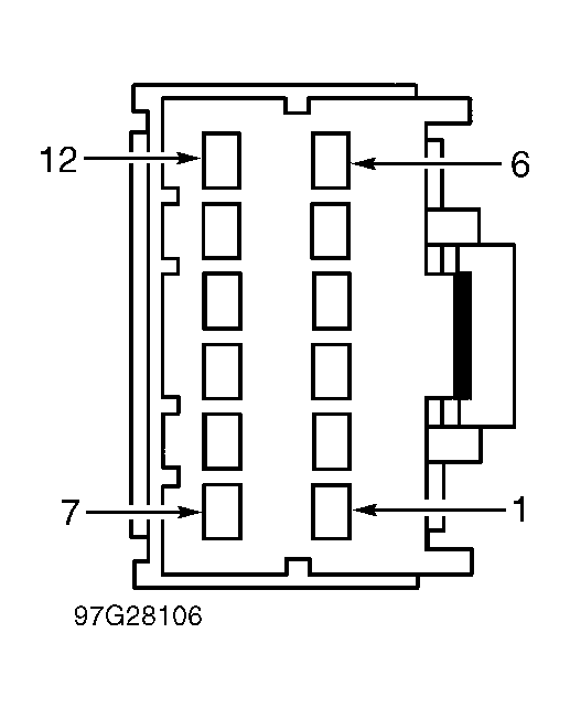 Courtesy of FORD MOTOR CO.