Test A: Unable To Enter Auto Test
- Recheck Procedure
Ensure air suspension is on. Repeat Auto Test. See AUTO TEST . If DTCs 211 through 228 are not displayed, go to next step. If DTCs 211 through 22 are displayed, go to step 8.
- Check For DTCs
Connect New Generation Star (NGS) tester or equivalent to diagnostic connector located on right shock tower. Perform Auto Test. See AUTO TEST . If no DTCs are displayed, go to next step. If DTCs are displayed, go to appropriate test and repair DTCs as necessary.
- Check Control Module Battery Circuits
Disconnect air suspension/EVO steering control module connector C204 (Black). See Figure. Turn ignition on. Measure voltage between ground and C204 pin No. 1 and No. 21 (Dark Green/Yellow wires) and C204 pin No. 4 (Purple/Orange wire). If battery voltage is present at all 3 pins, go to next step. If battery voltage is not present at one or both terminals, repair open Dark Green/Yellow or Purple/Orange wire and repeat Auto Test.
- Check Control Module Ground Circuits
Disconnect control module connector C205 (Gray). Measure resistance between ground and C205 pin No. 32 (Gray wire) and between ground and C204 pin No. 23 (Black/Light Green or Gray/Red wire). See Figure. If resistance of both circuits are less than 5 ohms, go to next step. If resistance of either circuit is greater than 5 ohms, repair open circuit and repeat Auto Test. See WIRING DIAGRAMS .
- Check Dark Green/Light Green Wire For Short To Ground
Measure voltage between ground and C205 pin No. 12 (Dark Green/Light Green wire). If 6 volts does not exist, go to next step. If 6 volts exists, go to step 7.
- Check Dark Green/Light Green Wire For Short
A short to ground in Dark Green/Light Green wire circuit will cause CHECK AIR RIDE to be displayed on message center even if no air suspension damage exists. Disconnect message center 16-pin connector. Measure resistance between ground and C204 pin No. 12 (Dark Green/Light Green wire). If resistance is less than 10 k/ohms, repair short to ground in Dark Green/Light Green wire. If resistance is greater than 10 k/ohms, message center is damaged. Repair as necessary.
- Check Dark Green/Light Green Wire For Open
Measure resistance of Dark Green/Light Green wire between diagnostic connector and C205 pin No. 12. If resistance is 5 ohms or less, go to next step. If resistance is greater than 5 ohms, repair open Dark Green/Light Green wire. Check system operation.
- Check Black/Light Green Wire Or Gray Wire For Open
Measure resistance of Black/Light Green wire (Gray wire on 1996 models) between diagnostic connector and C205 pin No. 32. See Figure. If resistance is 5 ohms or less, go to next step. If resistance is greater than 5 ohms, repair open Black/Light Green wire (Gray wire on 1996 models). Check system operation.
- Check Switch Continuity
Disconnect air suspension switch. Measure resistance between switch pins No. 1 and 3. See Fig 1. With air suspension switch in ON position. If resistance is less than 5 ohms, go to next step. If resistance is greater than 5 ohms, replace air suspension switch and repeat Auto Test.
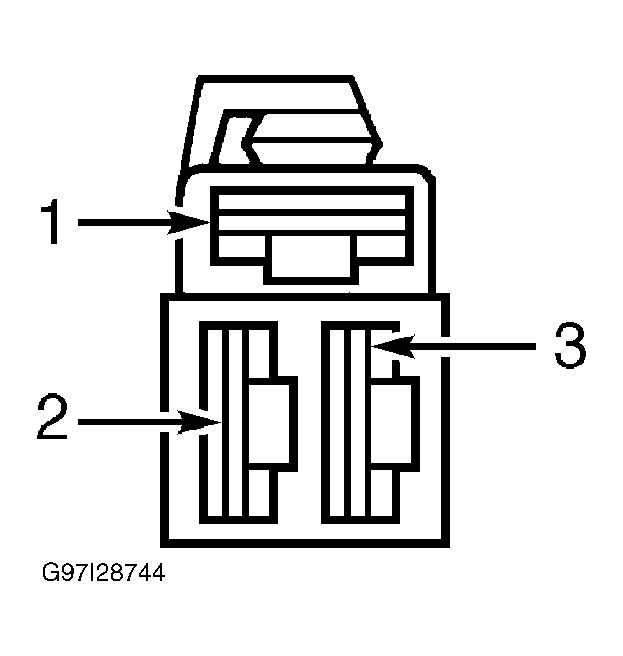 Courtesy of FORD MOTOR CO.
- Check Ground To Air Suspension Switch
Measure resistance between chassis ground and Black wire (Gray wire on 1996) at air suspension service switch connector. If resistance is 5 ohms or less, go to next step. If resistance is greater than 5 ohms, repair open Black wire (Gray wire on 1996 models). Check system operation.
- Check Brown/Pink Wire Circuit For Open
Disconnect control module connector C205 (Gray). Measure resistance of Brown/Pink wire between C204 pin No. 11 and air suspension switch connector. If resistance is greater than 5 ohms, repair open Brown/Pink wire. Check system operation. If resistance is 5 ohms or less, replace air suspension/EVO steering control module.