Diagnostic Procedure "A"
- Measure voltage between circuit No. 57 and appropriate circuits of lamp-out warning module connector. See Fig 1
. If voltage is 10-15 volts, go to step 2). Check circuits for high resistance or opens if voltage is less than 10 volts. Charge battery if necessary.
- Circuit No. 13 if problem is HEAD LAMP warning.
- Circuit No. 14 if problem is TAIL LAMP warning.
- Circuit No. 5 or circuit No. 9 if problem is BRAKE LAMP warning.
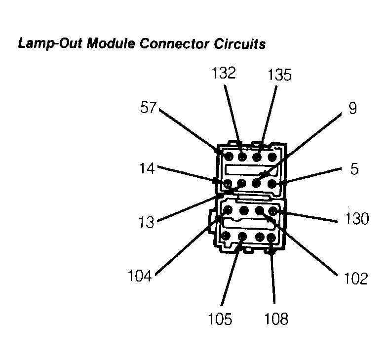 Courtesy of FORD MOTOR CO.
- Check for crossed circuits by energizing all circuits individually. Corresponding sense and reference terminals should be only terminals with voltage (9 volts minimum). If reference voltages are higher than sense voltages, go to step 3). Repair affected circuits if reference voltages are not higher than sense voltages.
- Measure voltage between appropriate terminals on harness connector. If voltages are as specified, replace lamp-out module. Go to step 4) if voltages are not as specified.
- Circuit No. 13 and circuit No. 108: .47 volt.
- Circuit No. 14 and circuit No. 102: .48 volt.
- Circuit No. 9 and circuit No. 104: .48 volt.
- Circuit No. 5 and circuit No. 104: .47 volt.
- Substitute new bulbs for those indicated by warning. Reconnect lamp-out module. Retest system. If okay, leave new bulbs in. If system does not operate properly, repair wiring harnesses to headlights, taillights and/or brakelights.