Pinpoint Test FQ
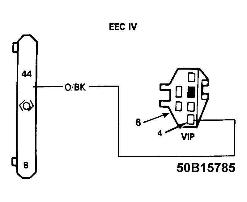 Courtesy of FORD MOTOR CO.
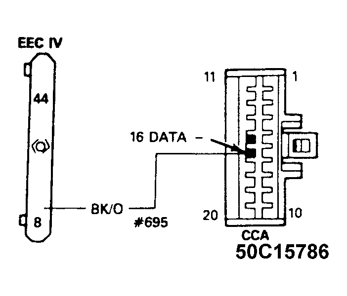 Courtesy of FORD MOTOR CO.
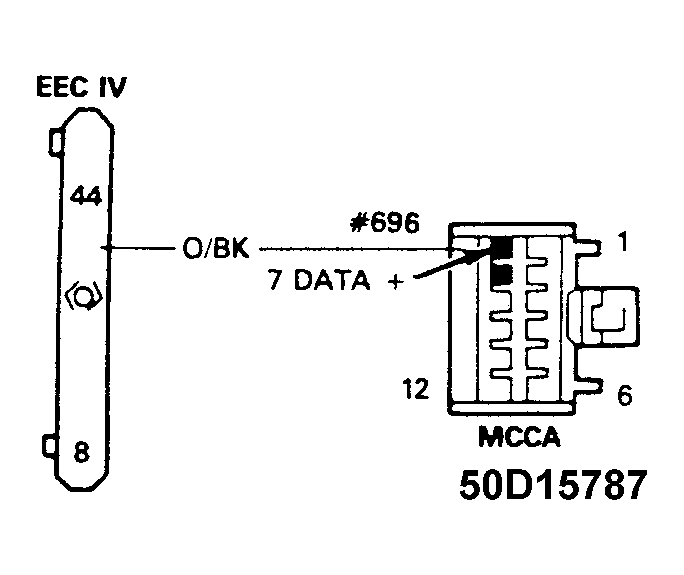 Courtesy of FORD MOTOR CO.
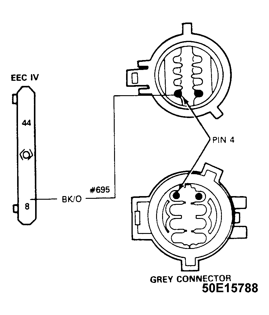 Courtesy of FORD MOTOR CO.
- Does CHECK ENGINE message appear? Turn ignition key to KEY ON/ENGINE ON position. Is CHECK ENGINE warning displayed? If yes, see appropriate test in SELF-DIAGNOSTICS - EEC-IV article in ENGINE PERFORMANCE. If no, go to step 2.
- Is CHECK DCL message being displayed on message center? If yes, go to step 3. If no, vehicle is OK.
- Are temperature gauge diagnostic bars displayed? If yes, go to step 8. If no, go to step 4.
- Check for a short or open between Pin 7 of MCCA and Pin 15 of CCA using an ohmmeter. If a short or open circuit exist, repair as required and go to step 28. If a short or open circuit does not exist, go to step 5.
- Inspect Pin 7 of MCCA and Pin 15 of CCA for damaged or corroded pins. If pins are corroded or damaged, repair as required and go to step 28. If pins are not corroded or damaged, go to step 6.
- Check for a short or open between Pin 8 of MCCA and Pin 16 of CCA using an ohmmeter. If a short or open circuit exist, repair as required and go to step 28. If a short or open circuit does not exist, go to step 7.
- Inspect Pin 8 of MCCA and Pin 16 of CCA for damaged or corroded pins. If pins are corroded or damaged, repair as required. If pins are not corroded or damaged, replace MCCA and go to step 28.
- Ground EEC-IV Self-Test Input Line. Place key in RUN position with the engine off. Does CHECK ENGINE warning appear on message center. If yes, go to step 9. If no, go to step 13.
- Check for a short or open between Pin 7 of MCCA and Pin 15 of CCA using an ohmmeter. If a short or open circuit exist, repair as required and go to step 28. If a short or open circuit does not exist, go to step 10.
- Inspect Pin 7 of MCCA and Pin 15 of CCA for damaged or corroded pins. If pins are corroded or damaged, repair as required and go to step 28. If pins are not corroded or damaged, go to step 11.
- Check for a short or open between Pin 8 of MCCA and Pin 16 of CCA using an ohmmeter. If a short or open circuit exist, repair as required and go to step 28. If a short or open circuit does not exist, go to step 12.
- Inspect Pin 8 of MCCA and Pin 16 of CCA for damaged or corroded pins. If pins are corroded or damaged, repair as required. If pins are not corroded or damaged, replace MCCA and go to step 28.
- Remove harness connector from EEC-IV module (10mm bolt retains connector to module.) Inspect Pins 8 and 44 on 60 pin connector (harness side and EEC-IV module side) for damaged or corroded pins. Are there any damaged or corroded pins or loose wires? If yes, repair as required and go to step 28. If no, go to step 14.
- Locate EEC-IV self test connector (in engine compartment near EEC-IV Module). Using DVOM 014-00407 or equivalent, check Circuit 696B for continuity and shorts to ground between Pin 44 of EEC-IV and Pin 4 of VIP connector. If circuit is OK, go to step 15. If circuit is not OK, repair as required and go to step 28.
- Locate EEC-IV self test connector (in engine compartment near EEC-IV Module). Using an ohmmeter, check Circuit 695B for continuity and shorts to ground between Pin 8 of EEC-IV connector and Pin 6 of VIP connector. If circuit is OK, go to step 16. If circuit is not OK, repair as required and go to step 28.
- Remove instrument cluster. Are any pins damaged/corroded or loose? If yes, repair as required and go to step 28. If no, go to step 17.
- Using an ohmmeter, check for short or open circuit between Pin 44 of EEC-IV connector and Pin 15 in CCA cluster connector (C2). Does connector wiring show continuity and no short condition? If yes, circuit is OK, go to step 18. If no, circuit is not OK, go to step 21.
- Using an ohmmeter, check for short or open circuit between Pin 8 of EEC-IV connector and Pin 16 in CCA cluster connector (C2). Does connector wiring show continuity and no short condition? If yes, circuit is OK, go to step 19. If no, circuit is not OK, go to step 21.
- Using an ohmmeter, check for short or open circuit between Pin 44 of EEC-IV connector and Pin 7 in message center connector (C1). Does connector wiring show continuity and no short condition? If yes, circuit is OK, go to step 20. If no, circuit is not OK, go to step 21.
- Using an ohmmeter, check for short or open circuit between Pin 8 of EEC-IV connector and Pin 8 in message center connector (C1). Does connector wiring show continuity and no short condition? If yes, circuit is OK, replace EEC-IV module and go to step 28. If no, circuit is not OK, go to step 21.
- Remove air cleaner (held in place by a 8mm bolt). Locate light Grey 8 pin connector under battery tray. Are there pushed pins, or corrosion on pins? If yes, repair as required and go to step 28. If no, go to step 22.
- Using an ohmmeter, check for short or open circuit between Pin 8 of EEC-IV connector and battery connector Pin 4. Does connector wiring show continuity and no short condition? If yes, go to step 23. If no, repair as required and go to step 28.
- Using an ohmmeter, check for short or open circuit between Pin 44 of EEC-IV connector and Pin 5 of battery feed connector. Does connector wiring show continuity and no short condition? If yes, go to step 24. If no, repair as required and go to step 28.
- Using an ohmmeter, check for short or open circuit between Pin 4 of battery connector and Pin 8 of MCCA connector (C1). Does connector wiring show continuity and no short condition? If yes, go to step 25. If no, repair as required and go to step 28.
- Using an ohmmeter, check for short or open circuit between Pin 4 of battery connector and Pin 16 of CCA connector (C2). Does connector wiring show continuity and no short condition? If yes, go to step 26. If no, repair as required and go to step 28.
- Using an ohmmeter, check for short or open circuit between Pin 5 of battery connector and Pin 7 of MCCA connector (C1). Does connector wiring show continuity and no short condition? If yes, go to step 27. If no, repair as required and go to step 28.
- Using an ohmmeter, check for short or open circuit between Pin 5 of battery connector and Pin 15 of CCA connector (C2). Does connector wiring show continuity and no short condition? If yes, go to step 28. If no, repair as required and go to step 28.
- Make sure EEC-IV Self Test Input (STI) line is no longer grounded (if instructed to do so in step 8). Verify that CCA/MCCA symptoms have been corrected. If system functions properly, system is OK. If system does not function properly, repeat test.