Caution / Notice / Hint
WARNING: This page is about a different car, the 2025 Lexus RX 450h+, 2025 Lexus RX 350h, 2024 Lexus RX 450h+, 2024 Lexus RX 350h, and 2023 Lexus RX 350h. However, it is still accessible from the selected car via links, so may be relevant.
The necessary procedures (adjustment, calibration, initialization or registration) that must be performed after parts are removed and installed, or replaced during fuel pump removal/installation are shown below.
NECESSARY PROCEDURES AFTER PARTS REMOVED/INSTALLED/REPLACED
| Replaced Part or Performed Procedure |
Necessary Procedure |
Effect/Inoperative Function when Necessary Procedure not Performed |
Link |
| Auxiliary battery terminal is disconnected/reconnected |
Operate the multiplex network master switch assembly (retractable outer mirror switch) to extend and retract the outer rear view mirror assembly |
Parking Support Brake System* |
Refer to INITIALIZATION [10/2022 - ] |
| Replacement of fuel pump |
Inspection after repair |
- Poor idle, etc.
- Engine start function, etc.
|
Refer to INITIALIZATION [10/2022 - ] |
*: When "[Parking Support Brake System icon] System Stopped See Owner's Manual" is displayed on the multi-information display.
WARNING:
- Never perform work on fuel system components near any possible ignition sources.
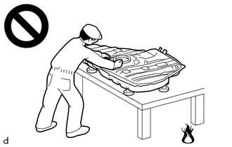 Courtesy of © TOYOTA, LICENSE AGREEMENT TMS1002 Courtesy of © TOYOTA, LICENSE AGREEMENT TMS1002
|
- Vaporized fuel could ignite, resulting in a serious accident.
- Do not perform work on fuel system components without first disconnecting the cable from the negative (-) auxiliary battery terminal.
 Courtesy of © TOYOTA, LICENSE AGREEMENT TMS1002 Courtesy of © TOYOTA, LICENSE AGREEMENT TMS1002
|
- Sparks could cause vaporized fuel to ignite, resulting in a serious accident.
NOTE:
To prevent the key from being locked in the vehicle, make sure to enter e-latch inspection mode and enable the manual release handle before disconnecting the cable from the negative (-) auxiliary battery terminal.
Refer to INSPECTION MODE PROCEDURE [10/2022 - ]
HINT:
When the cable is disconnected / reconnected to the auxiliary battery terminal, systems temporarily stop operating. However, each system has a function that completes learning the first time the system is used.
ITEMS FOR WHICH LEARNING IS COMPLETED BY DRIVING THE VEHICLE
| Effect/Inoperative Function when Necessary Procedure not Performed |
Necessary Procedure |
Link |
| Front Camera System |
Drive the vehicle straight ahead at 35 km/h (22 mph) or more for 5 second or more. |
Refer to INITIALIZATION [10/2022 - ] |
| Adaptive High Beam System |
| Lighting System (w/ Automatic Headlight Beam Level Control System) |
ITEMS FOR WHICH LEARNING IS COMPLETED BY OPERATING THE VEHICLE NORMALLY
| Effect/Inoperative Function when Necessary Procedure not Performed |
Necessary Procedure |
Link |
| Power Back Door System |
Reset back door close position |
Refer to INITIALIZATION [10/2022 - ] |
| Air Conditioning System |
After the ignition switch is turned to ON, the servo motor standard position is recognized. |
- |