Caution / Notice / Hint
WARNING: This page is about a different car, the 2025 Lexus RX 450h+, 2025 Lexus RX 350h, 2024 Lexus RX 450h+, 2024 Lexus RX 350h, and 2023 Lexus RX 350h. However, it is still accessible from the selected car via links, so may be relevant.
The necessary procedures (adjustment, calibration, initialization or registration) that must be performed after parts are removed and installed, or replaced during engine assembly removal/installation are shown below.
NECESSARY PROCEDURES AFTER PARTS REMOVED/INSTALLED/REPLACED
| Replaced Part or Performed Procedure |
Necessary Procedure |
Effect/Inoperative Function when Necessary Procedure not Performed |
Link |
| Auxiliary battery terminal is disconnected/reconnected |
Operate the multiplex network master switch assembly (retractable outer mirror switch) to extend and retract the outer rear view mirror assembly |
Parking Support Brake System*1 |
Refer to INITIALIZATION [10/2022 - ] |
| Replacement of ECM |
Perform Vehicle Identification Number (VIN) or frame number registration |
DTC is output |
Refer to REGISTRATION [10/2022 - ] |
| ECU configuration |
- |
Refer to ECU CONFIGURATION [10/2022 - ] |
| Update ECU security key |
Vehicle Control History (RoB) are stored |
Refer to UPDATE ECU SECURITY KEY [10/2022 - ] |
| Replacement of hybrid motor control inverter assembly |
Resolver learning |
- DTCs are stored
- Slight vibration at a vehicle speed of 5 km/h (3 mph) or less
- Shock or vibration during acceleration
|
Refer to UTILITY [08/2023 - ] |
| Replacement of hybrid vehicle transaxle assembly |
- Resolver learning
- Initialize resolver
|
- DTCs are stored
- Slight vibration at a vehicle speed of 5 km/h (3 mph) or less
- Shock or vibration during acceleration
|
Refer to UTILITY [08/2023 - ] |
| Tires |
- Initialization*2*3
- Tire Position Identification*2*3
|
Tire Pressure Warning System |
Refer to Procedures Necessary When Replacing Parts (for Tire Pressure Warning System)
Refer to WORK PROCEDURE [08/2023 - ] |
| Rear television camera assembly optical axis (Back camera position setting)*5 |
Parking Assist Monitor System |
Refer to CALIBRATION [10/2022 - ] |
| Parking assist ECU initialization*5 |
Panoramic View Monitor System |
Refer to CALIBRATION [10/2022 - ] |
| Advanced Park |
Refer to CALIBRATION [10/2022 - ] |
- Replacement of engine assembly
- Gas leak from exhaust system is repaired
|
Inspection after repair |
- Poor idle, etc.
- Engine start function, etc.
|
Refer to INITIALIZATION [10/2022 - ] |
| Replacement of front bumper assembly*4 |
Front television camera view adjustment |
Panoramic View Monitor System |
Refer to CALIBRATION [10/2022 - ] |
| Advanced Park |
Refer to CALIBRATION [10/2022 - ] |
| Suspension parts |
Rear television camera assembly optical axis (Back camera position setting) |
Parking Assist Monitor System |
Refer to CALIBRATION [10/2022 - ] |
| Parking assist ECU initialization |
Panoramic View Monitor System |
Refer to CALIBRATION [10/2022 - ] |
| Advanced Park |
Refer to CALIBRATION [10/2022 - ] |
| Perform headlight ECU sub-assembly LH initialization |
Lighting System (EXT) |
Refer to INITIALIZATION [10/2022 - ] |
| Front wheel alignment adjustment |
Perform "Calibration" |
- DTCs are stored
- ABS warning light illuminates
- Slip indicator light illuminates
- Electronically controlled brake system does not operate correctly
|
Refer to RESET MEMORY / CALIBRATION [08/2023 - ] |
*1: When "[Parking Support Brake System icon] System Stopped See Owner's Manual" is displayed on the multi-information display.
*2: Also necessary after performing a tire rotation.
*3: It is not necessary to perform this procedure if the tire pressure warning valve and transmitters are installed to the same location.
*4: Even when not replacing the part, it is necessary to perform the specified necessary procedures after installation.
*5: The vehicle height changes because of tire replacement.
WARNING:
- The engine assembly with transaxle is very heavy. Be sure to follow the procedure described in the appropriate service information
, or the engine lifter may suddenly drop or the engine assembly with transaxle may fall off the engine lifter.
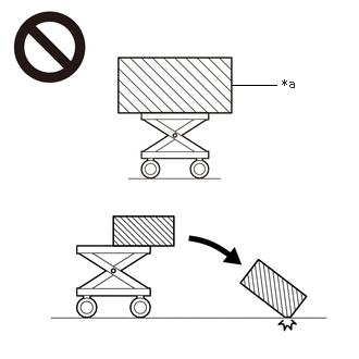 Courtesy of © TOYOTA, LICENSE AGREEMENT TMS1002 Courtesy of © TOYOTA, LICENSE AGREEMENT TMS1002
|
| *a |
An Object Exceeding Weight Limit of Engine Lifter |
- To prevent burns, do not touch the engine, exhaust manifold or other high temperature components while the engine is hot.
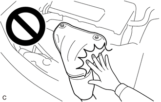 Courtesy of © TOYOTA, LICENSE AGREEMENT TMS1002 Courtesy of © TOYOTA, LICENSE AGREEMENT TMS1002
|
HINT:
When the cable is disconnected / reconnected to the auxiliary battery terminal, systems temporarily stop operating. However, each system has a function that completes learning the first time the system is used.
LEARNING COMPLETES WHEN VEHICLE IS DRIVEN
| Effect/Inoperative Function when Necessary Procedure not Performed |
Necessary Procedure |
Link |
| Front Camera System |
Drive the vehicle straight ahead at 35 km/h (22 mph) or more for 5 seconds or more. |
Refer to INITIALIZATION [10/2022 - ] |
| Adaptive High Beam System |
| Lighting System (EXT) |
LEARNING COMPLETES WHEN VEHICLE IS OPERATED NORMALLY
| Effect/Inoperative Function when Necessary Procedure not Performed |
Necessary Procedure |
Link |
| Power Back Door System |
Reset back door close position |
Refer to INITIALIZATION [10/2022 - ] |
| Air Conditioning System |
After the ignition switch is turned to ON, the servo motor and cooler expansion valve standard position is recognized. |
- |
COMPONENTS (REMOVAL)
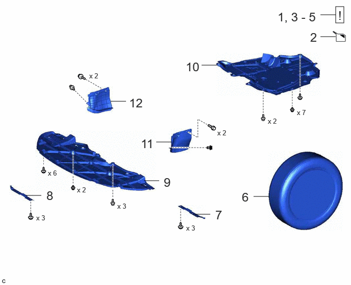 Courtesy of © TOYOTA, LICENSE AGREEMENT TMS1002
| Procedure |
Part Name Code |
 |
 |
 |
| 1 |
PRECAUTION |
- |
See step 1 |
- |
- |
| 2 |
RECOVER REFRIGERANT FROM REFRIGERATION SYSTEM |
- |
- |
See step 2 |
- |
| 3 |
DISCHARGE FUEL SYSTEM PRESSURE |
- |
See step 3 |
- |
- |
| 4 |
ALIGN FRONT WHEELS FACING STRAIGHT AHEAD |
- |
See step 4 |
- |
- |
| 5 |
SECURE STEERING WHEEL |
- |
See step 5 |
- |
- |
| 6 |
FRONT WHEELS |
- |
- |
- |
- |
| 7 |
FRONT WHEEL OPENING EXTENSION PAD LH |
53852B |
- |
- |
- |
| 8 |
FRONT WHEEL OPENING EXTENSION PAD RH |
53851D |
- |
- |
- |
| 9 |
NO. 1 ENGINE UNDER COVER |
51441 |
- |
- |
- |
| 10 |
NO. 2 ENGINE UNDER COVER ASSEMBLY |
51420 |
- |
- |
- |
| 11 |
FRONT FENDER APRON SEAL LH |
53737B |
- |
- |
- |
| 12 |
FRONT FENDER APRON SEAL RH |
53736 |
- |
- |
- |
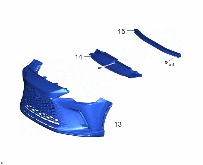 Courtesy of © TOYOTA, LICENSE AGREEMENT TMS1002
| Procedure |
Part Name Code |
|
|
|
| 13 |
FRONT BUMPER ASSEMBLY |
- |
- |
- |
- |
| 14 |
FRONT BUMPER LOWER ABSORBER |
52618 |
- |
- |
- |
| 15 |
NO. 2 FRONT BUMPER REINFORCEMENT |
52132A |
- |
- |
- |
 Courtesy of © TOYOTA, LICENSE AGREEMENT TMS1002
| Procedure |
Part Name Code |
|
|
|
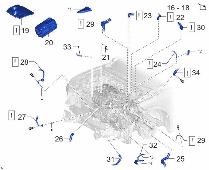
| 16 |
DRAIN ENGINE COOLANT (for Engine) |
- |
- |
See step 16 |
- |
| 17 |
DRAIN ENGINE OIL |
- |
- |
See step 17 |
- |
| 18 |
DRAIN HYBRID TRANSAXLE FLUID |
- |
- |
See step 18 |
- |
| 19 |
NO. 1 ENGINE COVER SUB-ASSEMBLY |
12601B |
See step 19 |
- |
- |
| 20 |
HYBRID MOTOR CONTROL INVERTER ASSEMBLY |
G92A0 |
- |
- |
- |
| 21 |
FUEL VAPOR FEED HOSE ASSEMBLY |
23820 |
- |
- |
- |
| 22 |
OUTLET HEATER WATER HOSE |
87246 |
See step 22 |
- |
- |
| 23 |
INLET HEATER WATER HOSE |
87245 |
See step 23 |
- |
- |
| 24 |
FUEL TUBE SUB-ASSEMBLY |
23901 |
See step 24 |
- |
- |
| 25 |
NO. 1 RADIATOR HOSE |
16571C |
- |
- |
- |
| 26 |
NO. 2 RADIATOR HOSE |
16572D |
- |
- |
- |
| 27 |
SUCTION HOSE SUB-ASSEMBLY |
88704 |
See step 27 |
- |
- |
| 28 |
DISCHARGE HOSE SUB-ASSEMBLY |
88703 |
See step 28 |
- |
- |
| 29 |
WIRE HARNESS |
- |
See step 29 |
- |
- |
| 30 |
FLOOR UNDER WIRE |
821H1 |
See step 30 |
- |
- |
| 31 |
NO. 5 INVERTER COOLING HOSE |
G9229A |
- |
- |
- |
| 32 |
NO. 1 TRANSMISSION OIL COOLER HOSE ASSEMBLY |
32930F |
- |
- |
- |
| 33 |
NO. 5 WATER BY-PASS HOSE |
16282F |
- |
- |
- |
| 34 |
STEERING INTERMEDIATE SHAFT ASSEMBLY |
45220 |
See step 34 |
- |
- |
| *1 |
NO. 1 RELAY BLOCK COVER |
*2 |
NO. 1 FUEL PIPE CLAMP |
| *3 |
INLET MOTOR HOSE |
*4 |
OUTLET MOTOR HOSE |
| • |
Non-reusable part |
- |
- |
 Courtesy of © TOYOTA, LICENSE AGREEMENT TMS1002
| Procedure |
Part Name Code |
|
|
|
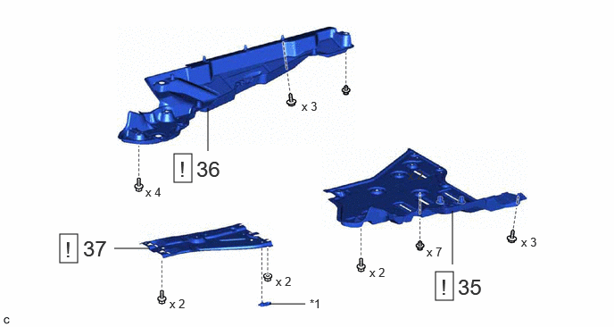
| 35 |
FRONT FLOOR COVER LH |
58166A |
See step 35 |
- |
- |
| 36 |
FRONT FLOOR COVER RH |
58165C |
See step 36 |
- |
- |
| 37 |
ENGINE UNDER COVER HEAT INSULATOR |
51468B |
See step 37 |
- |
- |
| *1 |
NO. 23 TRACTION BATTERY BRACKET |
- |
- |
 Courtesy of © TOYOTA, LICENSE AGREEMENT TMS1002
| Procedure |
Part Name Code |
|
|
|
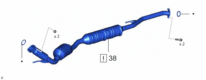
| 38 |
FRONT EXHAUST PIPE ASSEMBLY |
17410 |
See step 38 |
- |
- |
 Courtesy of © TOYOTA, LICENSE AGREEMENT TMS1002
| Procedure |
Part Name Code |
|
|
|
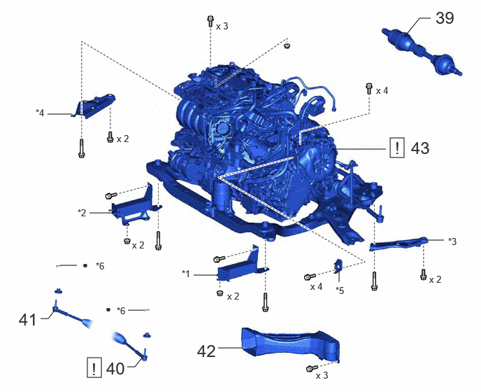
| 39 |
FRONT DRIVE SHAFT ASSEMBLY |
- |
- |
- |
- |
| 40 |
TIE ROD ASSEMBLY LH |
45470 |
See step 40 |
- |
- |
| 41 |
TIE ROD ASSEMBLY RH |
45460 |
- |
- |
- |
| 42 |
TRANSMISSION OIL COOLER AIR DUCT |
32917A |
- |
- |
- |
| 43 |
ENGINE ASSEMBLY WITH TRANSAXLE |
- |
See step 43 |
- |
- |
| *1 |
FRONT BUMPER EXTENSION SUB-ASSEMBLY LH |
*2 |
FRONT BUMPER EXTENSION SUB-ASSEMBLY RH |
| *3 |
FRONT SUSPENSION MEMBER BRACE REAR LH |
*4 |
FRONT SUSPENSION MEMBER BRACE REAR RH |
| *5 |
ENGINE MOUNTING STAY LH |
*6 |
COTTER PIN |
| • |
Non-reusable part |
- |
- |
 Courtesy of © TOYOTA, LICENSE AGREEMENT TMS1002
| Procedure |
Part Name Code |
|
|
|
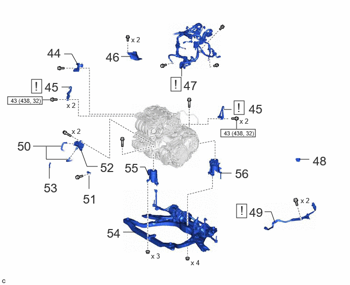
| 44 |
FUEL DELIVERY GUARD |
23825A |
- |
- |
- |
| 45 |
INSTALL ENGINE HANGERS |
- |
See step 45 |
- |
- |
| 46 |
STEERING GEAR HEAT INSULATOR |
45319 |
- |
- |
- |
| 47 |
DISCONNECT ENGINE WIRE |
82121 |
See step 47 |
- |
- |
| 48 |
FLYWHEEL HOUSING UNDER COVER |
11361J |
- |
- |
- |
| 49 |
HV AIR CONDITIONING WIRE |
821H2 |
See step 49 |
- |
- |
| 50 |
NO. 2 TRANSMISSION OIL COOLER HOSE ASSEMBLY |
32930G |
- |
- |
- |
| 51 |
WIRE HARNESS CLAMP BRACKET |
- |
- |
- |
- |
| 52 |
OIL PUMP WITH MOTOR ASSEMBLY |
35300B |
- |
- |
- |
| 53 |
FLYWHEEL HOUSING SIDE COVER |
11363A |
- |
- |
- |
| 54 |
FRONT FRAME ASSEMBLY |
51100G |
- |
- |
- |
| 55 |
FRONT ENGINE MOUNTING INSULATOR |
12361A |
- |
- |
- |
| 56 |
REAR ENGINE MOUNTING INSULATOR |
12371A |
- |
- |
- |
 |
N.m (kgf/cm, ft.lbf): Specified torque |
- |
- |
 Courtesy of © TOYOTA, LICENSE AGREEMENT TMS1002
| Procedure |
Part Name Code |
|
|
|
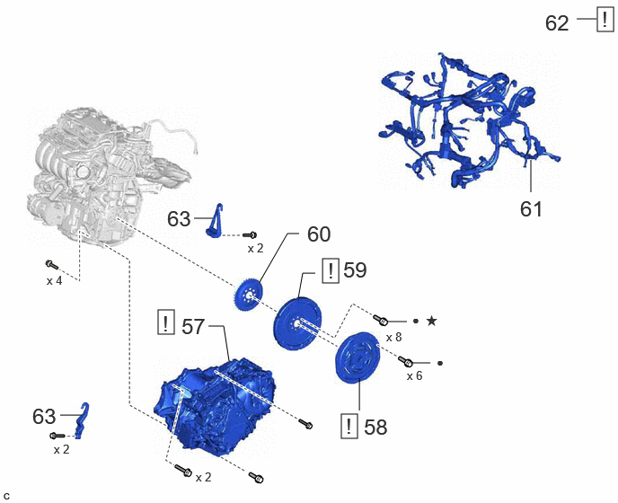
| 57 |
HYBRID VEHICLE TRANSAXLE ASSEMBLY |
30900 |
See step 57 |
- |
- |
| 58 |
TRANSMISSION INPUT DAMPER ASSEMBLY |
31270 |
See step 58 |
- |
- |
| 59 |
FLYWHEEL SUB-ASSEMBLY |
13405 |
See step 59 |
- |
- |
| 60 |
NO. 1 CRANKSHAFT POSITION SENSOR PLATE |
19315 |
- |
- |
- |
| 61 |
REMOVE ENGINE WIRE |
82121 |
- |
- |
- |
| 62 |
INSTALL ENGINE ASSEMBLY TO ENGINE STAND |
- |
See step 62 |
- |
- |
| 63 |
REMOVE ENGINE HANGERS |
- |
- |
- |
- |
| • |
Non-reusable part |
* |
Precoated part |
 Courtesy of © TOYOTA, LICENSE AGREEMENT TMS1002
| Procedure |
Part Name Code |
|
|
|
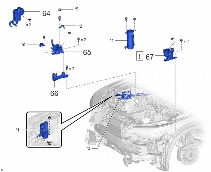
| 64 |
INVERTER RESERVE TANK ASSEMBLY |
G910GB |
- |
- |
- |
| 65 |
ENGINE MOUNTING INSULATOR SUB-ASSEMBLY RH |
12305 |
- |
- |
- |
| 66 |
ENGINE MOUNTING SPACER |
12341 |
- |
- |
- |
| 67 |
ENGINE MOUNTING INSULATOR SUB-ASSEMBLY LH |
12306 |
See step 67 |
- |
- |
| *1 |
RADIATOR RESERVE TANK ASSEMBLY |
*2 |
NO. 2 EARTH WIRE |
| *3 |
AIR CONDITIONING TUBE AND ACCESSORY ASSEMBLY |
*4 |
ACCUMULATOR ASSEMBLY |
| *5 |
EARTH BOLT CAP |
*6 |
NO. 1 INVERTER RESERVE TANK BRACKET |