Caution / Notice / Hint
The necessary procedures (adjustment, calibration, initialization, or registration) that must be performed after parts are removed and installed, or replaced during rear suspension member sub-assembly removal/installation are shown below.
NECESSARY PROCEDURES AFTER PARTS REMOVED/INSTALLED/REPLACED
| Replaced Part or Performed Procedure |
Necessary Procedure |
Effect/Inoperative Function when Necessary Procedure not Performed |
Link |
| Auxiliary battery terminal is disconnected/reconnected |
Operate the multiplex network master switch assembly (retractable outer mirror switch) to extend and retract the outer rear view mirror assembly |
Parking Support Brake System*1 |
Refer to INITIALIZATION [10/2022 - ] |
| Rear wheel alignment adjustment |
Perform "Calibration" |
- DTCs are stored
- ABS warning light illuminates
- Slip indicator light illuminates
- Electronically controlled brake system does not operate correctly
|
Refer to RESET MEMORY / CALIBRATION [10/2022 - ] |
w/ Dynamic Rear Steering:
- Rear Toe Adjustment
|
- DTCs are stored
- Steering neutral position deviate
|
Refer to Rear Toe Adjustment [10/2022 - ] |
| Suspension parts |
Rear television camera assembly optical axis (Back camera position setting) |
Panoramic View Monitor System |
Refer to CALIBRATION [10/2022 - ] |
| Parking assist ECU initialization |
Advanced Park |
Refer to CALIBRATION [10/2022 - ] |
| Perform headlight ECU sub-assembly LH initialization |
Lighting System (w/ Automatic Headlight Beam Level Control System) |
Refer to INITIALIZATION [10/2022 - ] |
| Tires |
- Initialization*2*3
- Tire Position Identification*2*3
|
Tire Pressure Warning System |
Refer to Procedures Necessary When Replacing Parts (for Tire Pressure Warning System) table below
Refer to WORK PROCEDURE [10/2022 - 08/2023]
, or refer to WORK PROCEDURE [08/2023 - ] |
| Rear television camera assembly optical axis (Back camera position setting)*4 |
Parking Assist Monitor System |
Refer to CALIBRATION [10/2022 - ] |
| Parking assist ECU initialization*4 |
Panoramic View Monitor System |
Refer to CALIBRATION [10/2022 - ] |
| Advanced Park |
Refer to CALIBRATION [10/2022 - ] |
| Rear height control sensor sub-assembly LH |
Perform headlight ECU sub-assembly LH initialization |
Lighting system (w/ Automatic Headlight Beam Level Control System) |
Refer to INITIALIZATION [10/2022 - ] |
| Gas leak from exhaust system is repaired |
Perform Inspection After Repair |
- Poor idle, etc.
- Engine start function, etc.
|
Refer to INITIALIZATION [10/2022 - ] |
*1: When "[Parking Support Brake System icon] System Stopped See Owner's Manual" is displayed on the multi-information display.
*2: Also necessary after performing a tire rotation.
*3: It is not necessary to perform this procedure if the tire pressure warning valve and transmitters are installed to the same location.
*4: The vehicle height changes because of tire replacement.
HINT:
When the cable is disconnected / reconnected to the auxiliary battery terminal, systems temporarily stop operating. However, each system has a function that completes learning the first time the system is used.
LEARNING COMPLETES WHEN VEHICLE IS DRIVEN
| Effect/Inoperative Function when Necessary Procedure not Performed |
Necessary Procedure |
Link |
| Front Camera System |
Drive the vehicle straight ahead at 35 km/h (22 mph) or more for 5 seconds or more. |
Refer to INITIALIZATION [10/2022 - ] |
| Adaptive High Beam System |
| Lighting System (w/ Automatic Headlight Beam Level Control System) |
LEARNING COMPLETES WHEN VEHICLE IS OPERATED NORMALLY
| Effect/Inoperative Function when Necessary Procedure not Performed |
Necessary Procedure |
Link |
| Power Back Door System |
Reset back door close position |
Refer to INITIALIZATION [10/2022 - ] |
| Air Conditioning System |
After the ignition switch is turned to ON, the servo motor standard position is recognized. |
- |
COMPONENTS (REMOVAL)
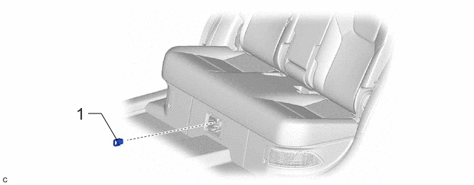 Courtesy of © TOYOTA, LICENSE AGREEMENT TMS1002
| Procedure |
Part Name Code |
 |
 |
 |
| 1 |
SERVICE PLUG GRIP |
G3834 |
- |
- |
- |
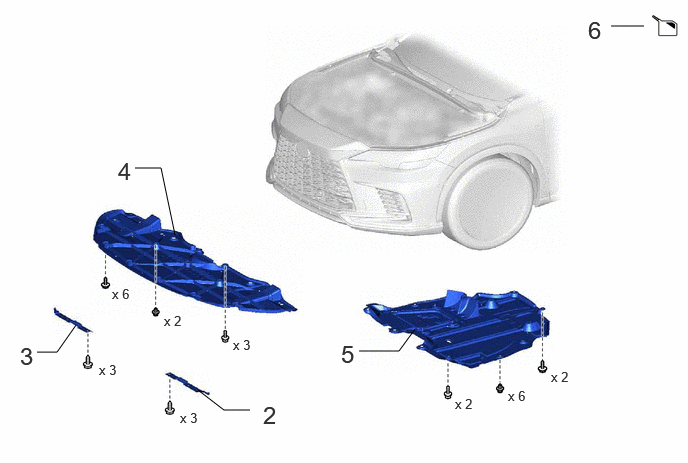 Courtesy of © TOYOTA, LICENSE AGREEMENT TMS1002
| Procedure |
Part Name Code |
|
|
|
| 2 |
FRONT WHEEL OPENING EXTENSION PAD LH |
53852B |
- |
- |
- |
| 3 |
FRONT WHEEL OPENING EXTENSION PAD RH |
53851D |
- |
- |
- |
| 4 |
NO. 1 ENGINE UNDER COVER |
51441 |
- |
- |
- |
| 5 |
NO. 2 ENGINE UNDER COVER ASSEMBLY |
51420 |
- |
- |
- |
| 6 |
DRAIN COOLANT (for Intercooler) |
- |
- |
See step 6 |
- |
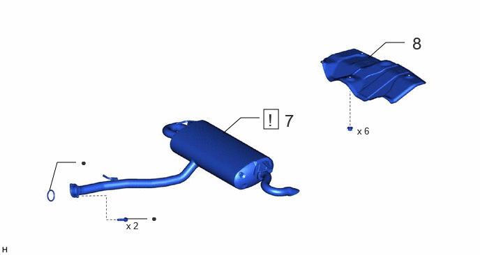 Courtesy of © TOYOTA, LICENSE AGREEMENT TMS1002
| Procedure |
Part Name Code |
|
|
|
| 7 |
TAIL EXHAUST PIPE ASSEMBLY |
17430 |
See step 7 |
- |
- |
| 8 |
LOWER MAIN MUFFLER HEAT INSULATOR |
58328B |
- |
- |
- |
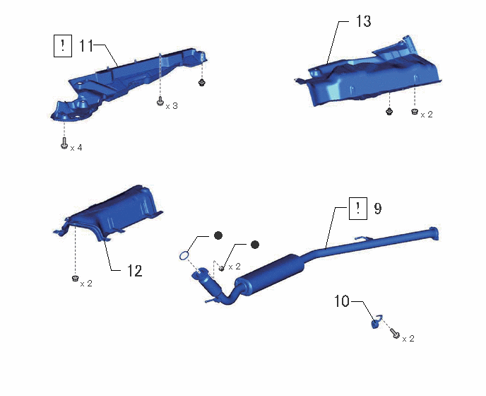 Courtesy of © TOYOTA, LICENSE AGREEMENT TMS1002
| Procedure |
Part Name Code |
|
|
|
| 9 |
FRONT EXHAUST PIPE ASSEMBLY |
17410 |
See step 9 |
- |
- |
| 10 |
NO. 2 EXHAUST PIPE SUPPORT BRACKET |
17572B |
- |
- |
- |
| 11 |
FRONT FLOOR COVER RH |
58165C |
See step 11 |
- |
- |
| 12 |
ENGINE SERVICE COVER ASSEMBLY |
58720B |
- |
- |
- |
| 13 |
REAR MAIN MUFFLER HEAT INSULATOR SUB-ASSEMBLY |
58043 |
- |
- |
- |
 Courtesy of © TOYOTA, LICENSE AGREEMENT TMS1002
| Procedure |
Part Name Code |
|
|
|
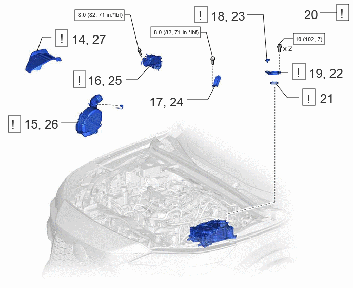
| 14 |
NO. 1 ENGINE COVER SUB-ASSEMBLY |
12601B |
See step 14 |
- |
- |
| 15 |
AIR CLEANER ASSEMBLY WITH NO. 1 AIR CLEANER HOSE |
- |
- |
- |
- |
| 16 |
AIR CLEANER HOSE ASSEMBLY |
17880 |
- |
- |
- |
| 17 |
INTAKE AIR CONNECTOR BRACKET |
17872 |
|
- |
- |
| 18 |
BATTERY COVER LOCK STRIKER |
G9295B |
See step 18 |
- |
- |
| 19 |
INVERTER TERMINAL COVER |
G9223 |
See step 19 |
- |
- |
| 20 |
TERMINAL VOLTAGE |
- |
See step 20 |
- |
- |
| 21 |
INVERTER TERMINAL GASKET |
G9233 |
See step 21 |
- |
- |
| 22 |
INVERTER TERMINAL COVER |
G9223 |
See step 22 |
- |
- |
| 23 |
BATTERY COVER LOCK STRIKER |
G9295B |
See step 23 |
- |
- |
| 24 |
INTAKE AIR CONNECTOR BRACKET |
17872 |
- |
- |
- |
| 25 |
AIR CLEANER HOSE ASSEMBLY |
17880 |
See step 25 |
- |
- |
| 26 |
AIR CLEANER ASSEMBLY WITH NO. 1 AIR CLEANER HOSE |
- |
See step 26 |
- |
- |
| 27 |
NO. 1 ENGINE COVER SUB-ASSEMBLY |
12601B |
See step 27 |
- |
- |
 Courtesy of © TOYOTA, LICENSE AGREEMENT TMS1002
| Procedure |
Part Name Code |
|
|
|
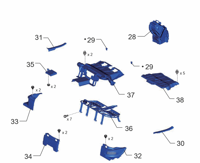
| 28 |
NO. 1 SPEAKER ASSEMBLY WITH BOX |
86150 |
- |
- |
- |
| 29 |
REAR SEAT CUSHION LOCK HOOK |
72693 |
- |
- |
- |
| 30 |
REAR DOOR SCUFF PLATE LH |
67918A |
- |
- |
- |
| 31 |
REAR DOOR SCUFF PLATE RH |
67917A |
- |
- |
- |
| 32 |
NO. 3 BATTERY SERVICE COVER BOARD |
58467J |
- |
- |
- |
| 33 |
NO. 2 BATTERY SERVICE COVER BOARD |
58466K |
- |
- |
- |
| 34 |
BATTERY SERVICE COVER BOARD |
58464D |
- |
- |
- |
| 35 |
FOLD SEAT CONTROL ECU |
89715 |
- |
- |
- |
| 36 |
REAR SEAT CUSHION LEG SUB-ASSEMBLY |
71033 |
- |
- |
- |
| 37 |
NO. 2 FLOOR MAT |
58512J |
- |
- |
- |
| 38 |
UPPER HV BATTERY COVER SUB-ASSEMBLY |
G920NB |
- |
- |
- |
 Courtesy of © TOYOTA, LICENSE AGREEMENT TMS1002
| Procedure |
Part Name Code |
|
|
|
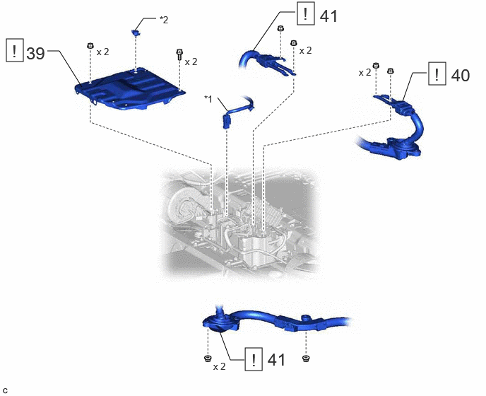
| 39 |
NO. 6 HV BATTERY SHIELD SUB-ASSEMBLY |
G920V |
See step 39 |
- |
- |
| 40 |
NO. 2 HV FLOOR UNDER WIRE |
821H6 |
See step 40 |
- |
- |
| 41 |
HV BATTERY CHARGER WIRE |
821H5A |
See step 41 |
- |
- |
| *1 |
HV Battery Wire |
*2 |
NO. 2 BATTERY COVER LOCK STRIKER |
 Courtesy of © TOYOTA, LICENSE AGREEMENT TMS1002
| Procedure |
Part Name Code |
|
|
|
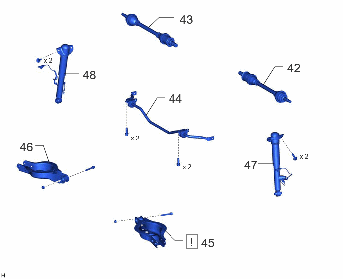
| 42 |
REAR DRIVE SHAFT ASSEMBLY LH |
42340B |
- |
- |
- |
| 43 |
REAR DRIVE SHAFT ASSEMBLY RH |
42330 |
- |
- |
- |
| 44 |
REAR STABILIZER BAR |
48812 |
- |
- |
- |
| 45 |
REAR NO. 2 SUSPENSION ARM ASSEMBLY LH |
48740F |
See step 45 |
- |
- |
| 46 |
REAR NO. 2 SUSPENSION ARM ASSEMBLY RH |
48730F |
- |
- |
- |
| 47 |
REAR SHOCK ABSORBER ASSEMBLY LH |
48540 |
- |
- |
- |
| 48 |
REAR SHOCK ABSORBER ASSEMBLY RH |
48530 |
- |
- |
- |
 Courtesy of © TOYOTA, LICENSE AGREEMENT TMS1002
| Procedure |
Part Name Code |
|
|
|
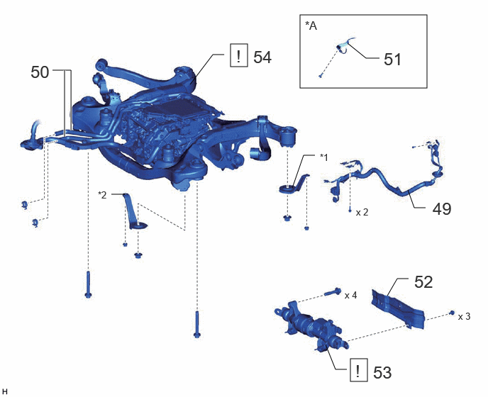
| 49 |
DISCONNECT FRAME WIRE |
82164 |
- |
- |
- |
| 50 |
NO. 1 INVERTER COOLING HOSE ASSEMBLY |
G90A0A |
- |
- |
- |
| 51 |
SEPARATE FRAME WIRE (w/ Height Control Sensor) |
82164 |
- |
- |
- |
| 52 |
STEERING GEAR HEAT INSULATOR |
45319B |
- |
- |
- |
| 53 |
REAR STEERING LINK ASSEMBLY |
45900 |
See step 53 |
- |
- |
| 54 |
REAR SUSPENSION MEMBER SUB-ASSEMBLY |
51206A |
See step 54 |
- |
- |
| *A |
w/ Height Control Sensor |
- |
- |
| *1 |
REAR SUSPENSION MEMBER REAR LOWER BRACE LH |
*2 |
REAR SUSPENSION MEMBER REAR LOWER BRACE RH |
| • |
Non-reusable part |
- |
- |
 Courtesy of © TOYOTA, LICENSE AGREEMENT TMS1002
| Procedure |
Part Name Code |
|
|
|
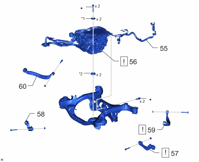
| 55 |
FRAME WIRE |
82164 |
- |
- |
- |
| 56 |
REAR TRANSAXLE WITH MOTOR AND INVERTER ASSEMBLY |
30610A |
See step 56 |
- |
- |
| 57 |
REAR UPPER CONTROL ARM ASSEMBLY LH |
48790 |
See step 57 |
- |
- |
| 58 |
REAR UPPER CONTROL ARM ASSEMBLY RH |
48770A |
- |
- |
- |
| 59 |
REAR UPPER NO. 2 CONTROL ARM ASSEMBLY LH |
48790F |
See step 59 |
- |
- |
| 60 |
REAR UPPER NO. 2 CONTROL ARM ASSEMBLY RH |
48790E |
- |
- |
- |
| *1 |
UPPER DIFFERENTIAL MOUNT STOPPER |
*2 |
LOWER DIFFERENTIAL MOUNT STOPPER |
| • |
Non-reusable part |
- |
- |
 Courtesy of © TOYOTA, LICENSE AGREEMENT TMS1002
| Procedure |
Part Name Code |
|
|
|
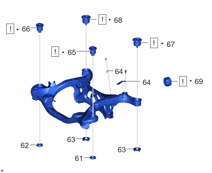
| 61 |
REAR SUSPENSION MENBER LOWER STOPPER RETAINER LH |
52278A |
- |
- |
- |
| 62 |
REAR SUSPENSION MEMBER LOWER STOPPER RETAINER RH |
52277A |
- |
- |
- |
| 63 |
REAR LOWER REAR SUSPENSION MEMBER STOPPER |
52278C |
- |
- |
- |
| 64 |
WIRE HARNESS CLAMP BRACKET |
- |
- |
- |
- |
| 65 |
REAR SUSPENSION MEMBER FRONT BODY MOUNTING CUSHION LH |
52272A |
See step 65 |
- |
- |
| 66 |
REAR SUSPENSION MEMBER FRONT BODY MOUNTING CUSHION RH |
52271E |
See step 66 |
- |
- |
| 67 |
REAR SUSPENSION MEMBER REAR BODY MOUNT CUSHION LH |
52276A |
See step 67 |
- |
- |
| 68 |
REAR SUSPENSION MEMBER REAR BODY MOUNT CUSHION RH |
52275B |
See step 68 |
- |
- |
| 69 |
REAR MOTOR MOUNTING INSULATOR |
G2371A |
See step 69 |
- |
- |