Installation (08/2010 - 08/2011): Installation
- INSTALL COMBINATION METER ASSEMBLY
- Connect the connector.
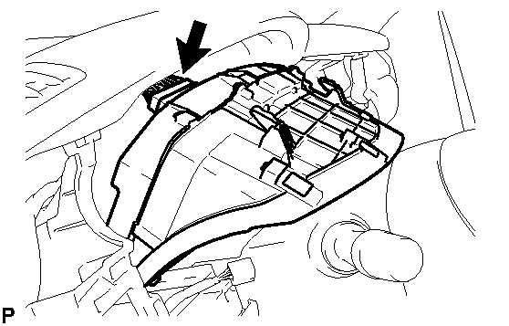 Courtesy of © TOYOTA, LICENSE AGREEMENT TMS1002
- Attach the 2 clips.
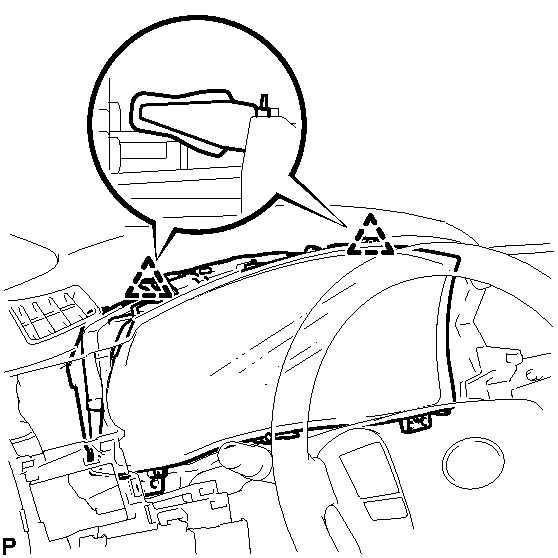 Courtesy of © TOYOTA, LICENSE AGREEMENT TMS1002
- Install the combination meter with the 2 screws.
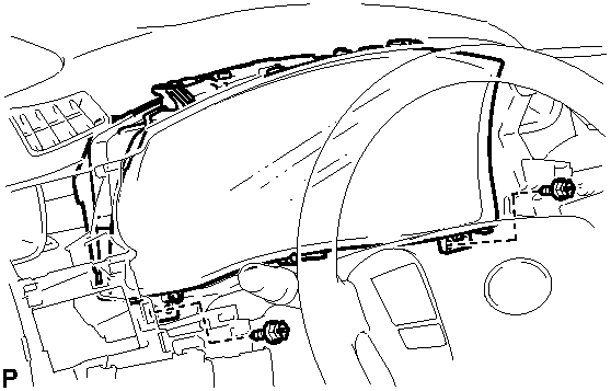 Courtesy of © TOYOTA, LICENSE AGREEMENT TMS1002
- INSTALL NO. 3 INSTRUMENT PANEL REGISTER ASSEMBLY
- Attach the 5 claws to install the register.
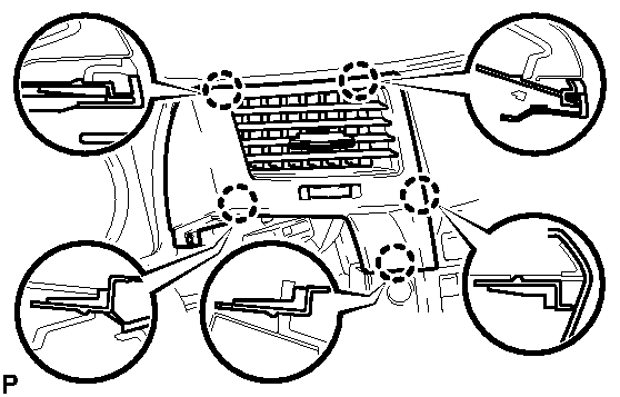 Courtesy of © TOYOTA, LICENSE AGREEMENT TMS1002
- INSTALL NO. 1 INSTRUMENT PANEL REGISTER ASSEMBLY
- Attach the 4 claws to install the register.
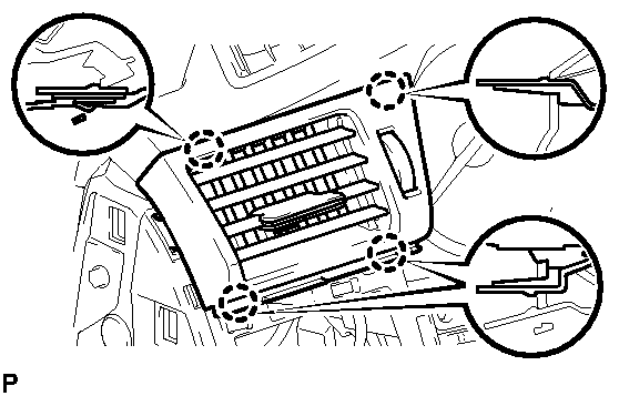 Courtesy of © TOYOTA, LICENSE AGREEMENT TMS1002
- INSTALL INSTRUMENT CLUSTER FINISH PANEL SUB-ASSEMBLY
- Connect the connectors.
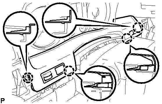 Courtesy of © TOYOTA, LICENSE AGREEMENT TMS1002
- Attach the 4 claws to install the finish panel.
- Attach the 6 claws.
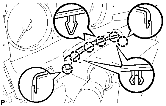 Courtesy of © TOYOTA, LICENSE AGREEMENT TMS1002
- INSTALL LOWER INSTRUMENT PANEL PAD SUB-ASSEMBLY LH
- Connect the connector.
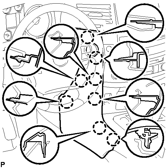 Courtesy of © TOYOTA, LICENSE AGREEMENT TMS1002
- Attach the 8 claws to install the instrument panel pad.
- INSTALL NO. 1 SWITCH HOLE BASE
- Connect the connectors.
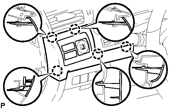 Courtesy of © TOYOTA, LICENSE AGREEMENT TMS1002
- Attach the 5 claws to install the hole base.
- INSTALL INSTRUMENT SIDE PANEL LH
- Attach the 6 claws to install the side panel.
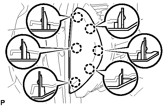 Courtesy of © TOYOTA, LICENSE AGREEMENT TMS1002
- CONNECT CABLE TO NEGATIVE BATTERY TERMINAL
NOTE:
- Reset the Autoaway/Return function setting to the previous condition by changing the customize parameter. Refer to CUSTOMIZE PARAMETERS
.
- When disconnecting the cable, some systems need to be initialized after the cable is reconnected. Refer to INITIALIZATION
.
- INSTALL ENGINE ROOM SIDE COVER LH
. Refer to INSTALLATION - Step 3