Reassembly
AXLE AND DIFFERENTIAL: REAR DIFFERENTIAL CARRIER ASSEMBLY: REASSEMBLY
1. ASSEMBLE DIFFERENTIAL CASE
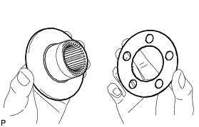
(a) Install the rear differential side gear thrust washer to the rear differential side gear.
(b) Install the rear differential pinion thrust washer and rear differential pinion to the rear differential spider.
(c) Fix the differential case RH in place.
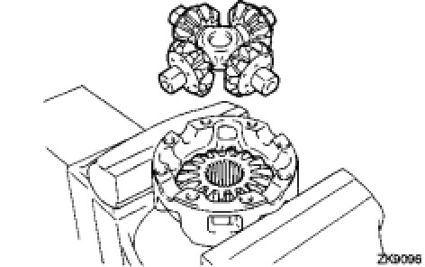
Install the rear differential side gear and rear differential spider to the differential case RH.
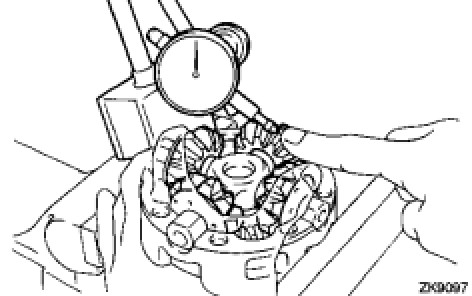
Using a dial indicator, measure the differential case RH side backlash while pushing the pinion toward the case.
Standard backlash:
0.05 to 0.20 mm (0.00197 to 0.00787 in.)
(d) Remove the rear differential spider from the differential case RH.
(e) Install the rear differential side gear and rear differential spider to the differential case LH.
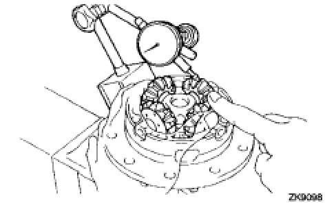
Using a dial indicator, measure the differential case LH side backlash while pushing the pinion toward the case.
Standard backlash:
0.05 to 0.20 mm (0.00197 to 0.00787 in.)
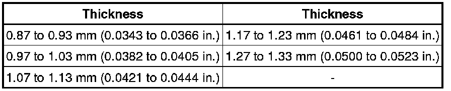
If the backlash is not within the specification, install 2 side gear thrust washers of a different thickness.
Standard Thrust Washer:
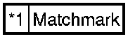
(f) Align the matchmarks and assemble the differential case from the RH and LH cases.
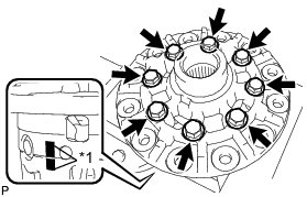
Text in Illustration
(g) Using a plastic-faced hammer, install the differential case.
(h) Install the 8 bolts.
Torque : 47 Nm (480 kgf-cm, 35 ft-lbf)
2. INSTALL DIFFERENTIAL RING GEAR
(a) Clean the contact surfaces of the differential case and ring gear.
(b) Heat the ring gear in water that is approximately 100°C (212°F).
(c) Carefully remove the ring gear from the boiling water.
(d) After the moisture on the ring gear has completely evaporated, quickly install the ring gear to the differential case.
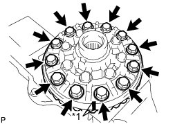
Align the matchmarks on the ring gear with that of the differential case.
Text in Illustration
(e) After the ring gear cools down sufficiently, apply adhesive to the 12 bolts and install them.
Adhesive:
Toyota Genuine Adhesive 1360K, Three Bond 1360K or equivalent
Torque : 97 Nm (985 kgf-cm, 71 ft-lbf)
3. INSTALL REAR DIFFERENTIAL CASE BEARING
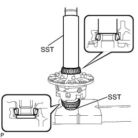
(a) Using SST and a press, press the bearing onto the differential case.
SST : 09308-14010
SST : 09950-60010
09951-00490
4. INSPECT DIFFERENTIAL RING GEAR RUNOUT
(a) Install the differential case to the carrier and install the 2 adjusting nuts so that there is no play in the bearing.
(b) Install the 2 bearing caps with the 4 bolts.
Torque : 103 Nm (1049 kgf-cm, 76 ft-lbf)
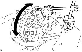
Using a dial indicator, measure the runout of the ring gear.
Maximum runout:
0.07 mm (0.00276 in.)
(c) Remove the 2 bearing caps, 2 adjusting nuts and differential case.
5. INSTALL REAR DRIVE PINION FRONT TAPERED ROLLER BEARING (OUTER)
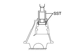
(a) Using SST and a press, press in the roller bearing (outer) to the carrier.
SST : 09308-14010
SST : 09309-14040
6. INSTALL REAR DRIVE PINION REAR TAPERED ROLLER BEARING (OUTER)
(a) Install the plate washer to the carrier.
HINT
First, install a washer with the same thickness as the removed washer, and then check the tooth contact pattern. Replace the washer with one of a different thickness if necessary.
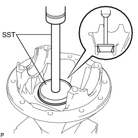
(b) Using SST and a press, press the roller bearing (outer) into the carrier.
SST : 09950-70010
09951-07200
SST : 09255-10012
7. INSTALL REAR DRIVE PINION REAR TAPERED ROLLER BEARING (INNER)
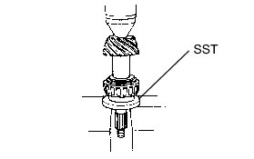
(a) Using SST and a press, press the roller bearing (inner) onto the drive pinion.
SST : 09309-14040
8. ADJUST DIFFERENTIAL DRIVE PINION PRELOAD
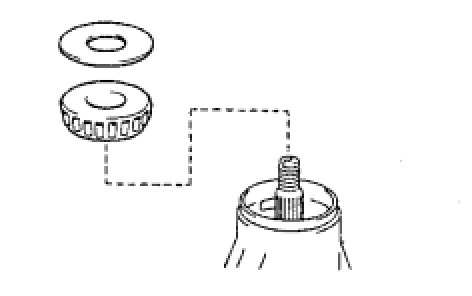
(a) Install the drive pinion, rear drive pinion tapered roller bearing and rear differential drive pinion oil slinger.
HINT
Install the spacer and oil seal after adjusting the gear contact pattern.
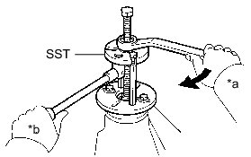
Using SST, install the companion flange.
SST : 09950-30012
09951-03010
09953-03010
09954-03010
09955-03030
09956-03040
Text in Illustration
NOTICE:
Before using SST (center bolt), apply hypoid gear oil to its threads and tip.
(b) Using a 30 mm socket wrench, adjust the drive pinion preload by tightening the companion flange nut.
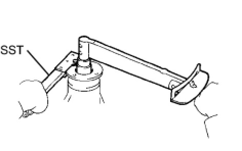
Using SST to hold the companion flange in place, tighten the nut.
SST : 09330-00021
Torque : 457 Nm (4660 kgf-cm, 337 ft-lbf) or less
NOTICE:
* As there is no spacer, tighten the nut a little at a time. Be careful not to overtighten the nut.
* Apply LSD oil to the nut.
(c) Using a torque wrench, measure the preload.
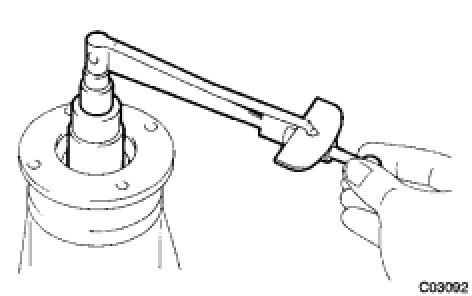
Standard Preload (at Starting):

NOTICE:
For a more accurate measurement, rotate the bearing forward and backward several times before measuring.
9. INSTALL DIFFERENTIAL CASE ASSEMBLY
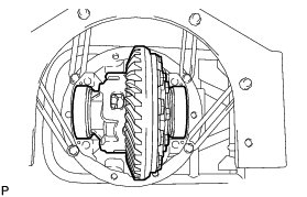
(a) Place the 2 bearing outer races on their respective bearings.
HINT
Do not interchange the right and left races.
10. ADJUST RING GEAR BACKLASH
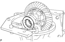
(a) Install the plate washer on the side without the ring gear teeth.
NOTICE:
Make sure that the ring gear has backlash.
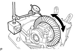
(b) Using a dial indicator, while holding the companion flange, measure the ring gear backlash.
Standard backlash (reference):
0.10 to 0.20 mm (0.00394 to 0.00787 in.)
(c) Select a plate washer for the side with the ring gear teeth using the backlash as a reference.
(d) Select a plate washer for the side without the ring gear teeth so that there is no clearance between the outer race and case.
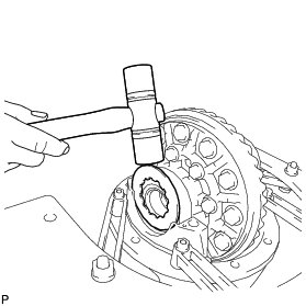
(e) Using a plastic-faced hammer, install the plate washer for the side without the ring gear teeth.
(f) Using a dial indicator, while holding the companion flange, measure the ring gear backlash.
Standard backlash:
0.10 to 0.20 mm (0.00394 to 0.00787 in.)
If the backlash is not within the specification, adjust it by either increasing or decreasing the thickness of the washers on both sides by an equal amount.
HINT
* There should be no clearance between the plate washer and case.
* Make sure that there is ring gear backlash.
11. ADJUST SIDE BEARING PRELOAD
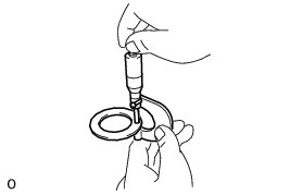
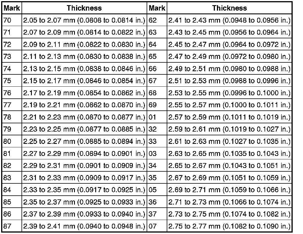
(a) Remove the ring gear teeth side plate washer and, using a micrometer, measure the thickness.
(b) Using the backlash as a reference, select a new washer that is 0.05 to 0.20 mm (0.00197 to 0.00787 in.) thicker than the removed washer and, using a plastic-faced hammer, tap it in so that it fits against the bearing.
HINT
Select a washer which can be pressed in 2/3 of the full amount with your finger.
(c) Recheck the ring gear backlash.
Standard backlash:
0.10 to 0.20 mm (0.00394 to 0.00788 in.)
If the backlash is not within the specification, adjust it by either increasing or decreasing the thickness of the washers on both sides by an equal amount.
HINT
An approximately 0.02 mm (0.000787 in.) change in each plate washer results in a 0.03 mm (0.00118 in.) change in the backlash.
Standard Washer:
12. INSTALL BEARING CAP
(a) Align the matchmarks on the cap and carrier.
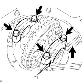
Text in Illustration
(b) Install the 2 bearing caps with the 4 bolts.
Torque : 103 Nm (1049 kgf-cm, 76 ft-lbf)
HINT
After rotating the ring gear 5 times or more, recheck the backlash.
13. INSPECT DIFFERENTIAL RING GEAR RUNOUT
(a) Using a dial indicator, measure the runout of the ring gear.
Maximum runout:
0.07 mm (0.00276 in.)
If the runout is more than the maximum, replace the ring gear.
14. INSPECT TOTAL PRELOAD
(a) Using a torque wrench, measure the preload with the teeth of the drive pinion and ring gear in contact.
Standard total preload (at starting):
Drive pinion preload plus 0.20 to 0.40 N*m (2 to 4 kgf*cm, 2 to 3 in.*lbf)
If necessary, disassemble and inspect the differential.
15. INSPECT TOOTH CONTACT BETWEEN RING GEAR AND DRIVE PINION
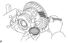
(a) Coat 3 or 4 teeth at 3 different positions on the ring gear with Prussian blue.
(b) Hold the companion flange firmly in place and rotate the ring gear in both directions.
(c) Inspect the tooth contact pattern.
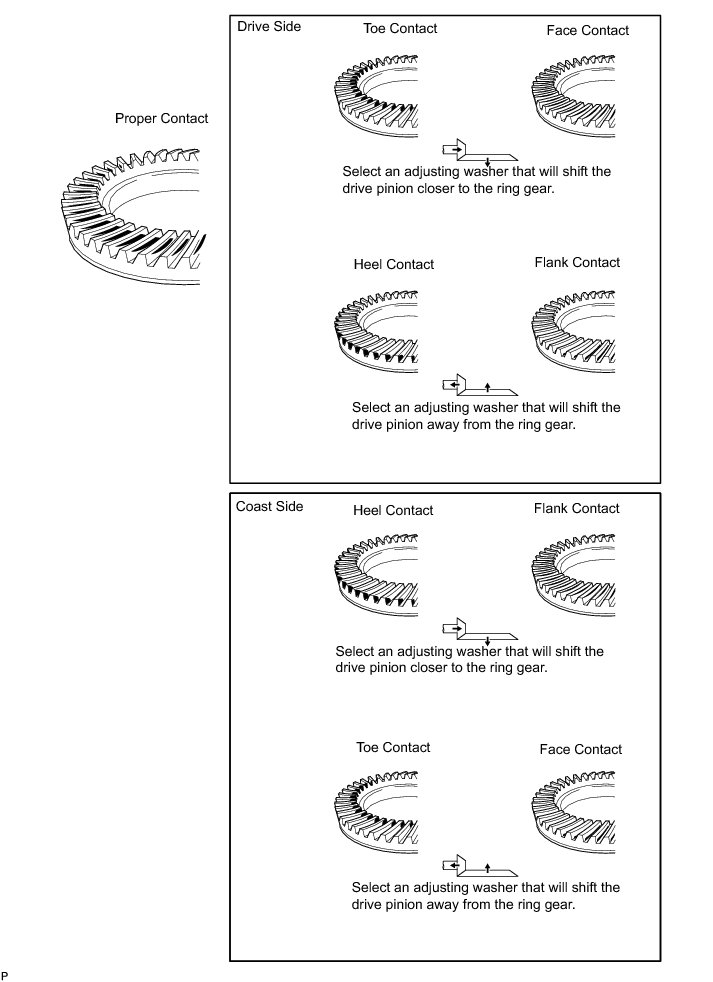
If the teeth are not engaged properly, use the following chart to select a proper washer.
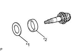
Text in Illustration

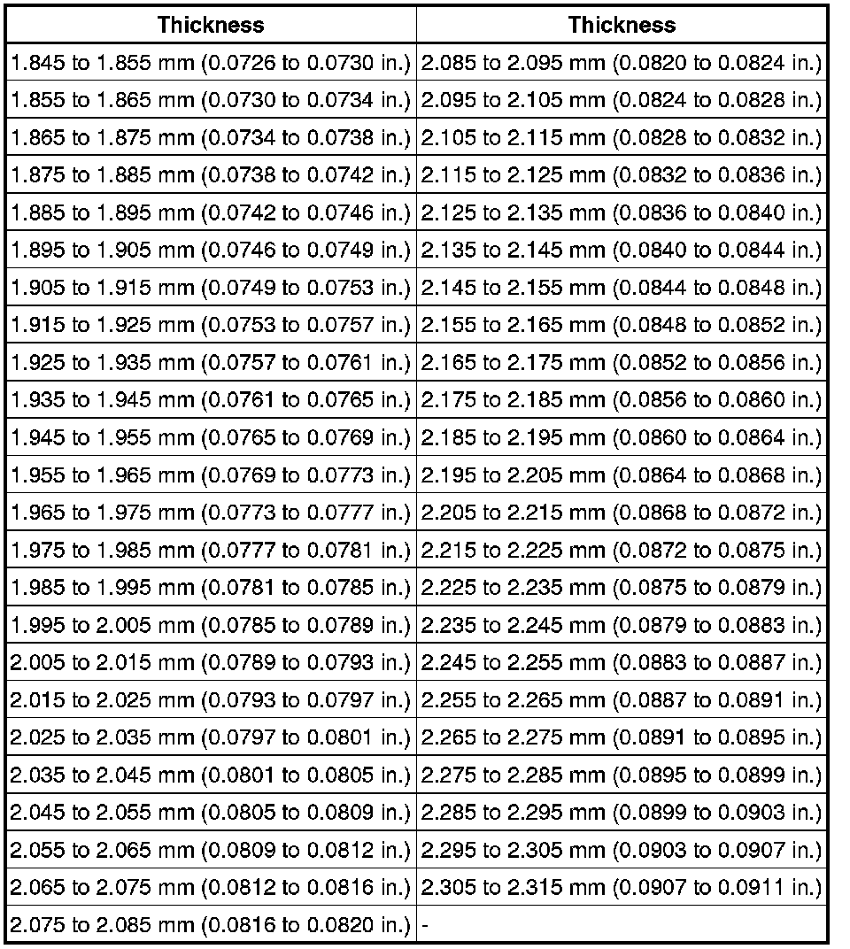
Standard Plate Washer:
16. REMOVE REAR DRIVE PINION NUT
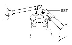
(a) Using SST to hold the companion flange in place, remove the nut.
SST : 09330-00021
09330-00030
17. REMOVE REAR DRIVE PINION COMPANION FLANGE SUB-ASSEMBLY Replacement
18. REMOVE REAR DIFFERENTIAL DRIVE PINION OIL SLINGER
19. REMOVE REAR DRIVE PINION FRONT TAPERED ROLLER BEARING (INNER) Replacement
20. REMOVE REAR DRIVE PINION FRONT TAPERED ROLLER BEARING (OUTER)
21. INSTALL REAR DIFFERENTIAL DRIVE PINION BEARING SPACER
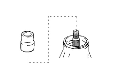
(a) Install a new bearing spacer to the drive pinion.
22. INSTALL DIFFERENTIAL OIL STORAGE RING
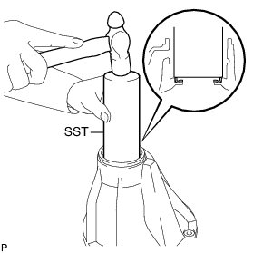
(a) Using SST, tap in a new oil storage ring.
SST : 09308-14010
23. INSTALL REAR DRIVE PINION FRONT TAPERED ROLLER BEARING (OUTER)
24. INSTALL REAR DRIVE PINION FRONT TAPERED ROLLER BEARING (INNER)
25. INSTALL REAR DIFFERENTIAL DRIVE PINION OIL SLINGER
26. INSTALL REAR DIFFERENTIAL CARRIER OIL SEAL
(a) Apply MP grease to the lip of a new oil seal.
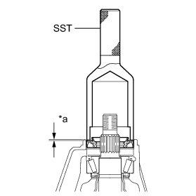
Using SST and a hammer, tap in the oil seal.
SST : 09554-30011
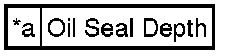
Standard oil seal depth:
-0.3 to 0.3 mm (-0.0118 to 0.0118 in.)
Text in Illustration
27. INSTALL REAR DRIVE PINION COMPANION FLANGE SUB-ASSEMBLY
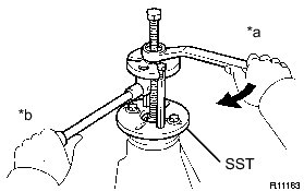
(a) Using SST, install the companion flange to the drive pinion.
SST : 09950-30012
09951-03010
09953-03010
09954-03010
09955-03030
09956-03040
Text in Illustration
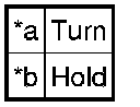
NOTICE:
Before using SST (center bolt), apply hypoid gear oil to its threads and tip.
(b) Coat the threads of a new nut with LSD.
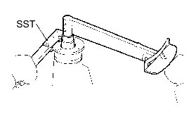
Using SST to hold the flange, tighten the nut.
SST : 09330-00021
09330-00030
Torque : 457 Nm (4660 kgf-cm, 337 ft-lbf) or less
28. INSPECT DRIVE PINION PRELOAD
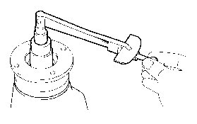
(a) Using a torque wrench, measure the preload of the backlash between the drive pinion and ring gear.
Standard Preload (at Starting):

If the result not as specified, replace the bearing spacer.
If the preload is less than the minimum, retighten the nut with 13 N*m (130 kgf*cm, 9 ft.*lbf) of torque at a time until the specified preload is reached.
Torque : 457 Nm (4660 kgf-cm, 337 ft-lbf) or less
If the maximum torque is exceeded while retightening the nut, replace the bearing spacer and repeat the preload adjusting procedure.
HINT
Do not loosen the pinion nut to reduce the preload.
29. INSPECT TOTAL PRELOAD
(a) Using a torque wrench, measure the preload with the teeth of the drive pinion and ring gear in contact.
Standard total preload (at starting):
Drive pinion preload plus 0.20 to 0.40 N*m (2.0 to 4.1 kgf*cm, 1.8 to 3.5 in.*lbf)
If necessary, disassemble and inspect the differential.
30. INSPECT DIFFERENTIAL RING GEAR BACKLASH
(a) Using a dial indicator, measure the backlash of the ring gear.
Standard backlash:
0.10 to 0.20 mm (0.00394 to 0.00787 in.)
If the backlash is not as specified, adjust the side bearing preload or perform repairs as necessary.
HINT
Perform the measurement at 3 or more positions around the circumference of the ring gear.
31. INSPECT RUNOUT OF REAR DRIVE PINION COMPANION FLANGE SUB-ASSEMBLY
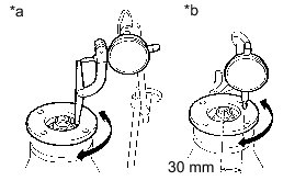
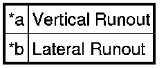
(a) Using a dial indicator, measure the runout of the drive pinion companion flange vertically and laterally.
Distance from center to runout measurement point:
30 mm (1.18 in.)
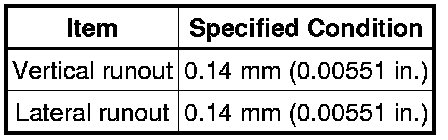
Maximum Runout:
Text in Illustration
If the runout is more than the maximum, replace the companion flange.
32. STAKE DRIVE PINION NUT
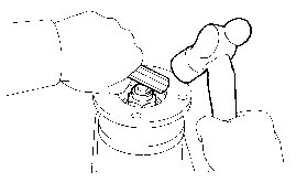
(a) Using a chisel and hammer, stake the nut.