Part 4
A760F AUTOMATIC TRANSMISSION / TRANSAXLE: AUTOMATIC TRANSMISSION UNIT: REASSEMBLY
71. INSTALL REAR TRANSFER ADAPTER
(a) Install the transfer adapter hole snap ring.
(b) Clean the threads of the bolts and transfer adapter.
(c) Apply seal packing or equivalent to the transfer adapter.
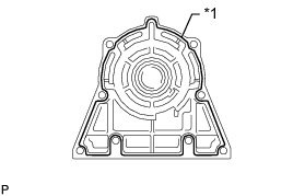
Seal packing:
Toyota Genuine Seal Packing 1281,
Three Bond 1281 or equivalent
Seal diameter:
1.0 to 1.5 mm (0.0394 to 0.0591 in.)
(d) Apply adhesive to the threads of the 8 bolts.
Adhesive:
Toyota Genuine Adhesive 1324,
Three Bond 1324 or equivalent
(e) Install the extension housing with the 6 bolts.
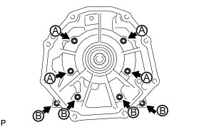
Torque : 34 Nm (345 kgf-cm, 25 ft-lbf)
HINT
Each bolt length is indicated below.
50 mm (1.97 in.) for bolt A
40 mm (1.57 in.) for bolt B
72. INSTALL AUTOMATIC TRANSMISSION HOUSING
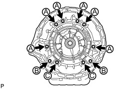
(a) Clean the threads of the bolts and case with non-residue solvent.
(b) Apply adhesive to the threads of the 4 bolts labeled B and C.
Adhesive:
Toyota Genuine Adhesive 1324,
Three Bond 1324 or equivalent
(c) Install the transmission housing with the 10 bolts.
for bolt A and C (14 mm head) - Torque : 34 Nm (345 kgf-cm, 25 ft-lbf
for bolt B (17 mm head) - Torque : 57 Nm (579 kgf-cm, 42 ft-lbf
73. INSTALL AUTOMATIC TRANSMISSION BREATHER TUBE
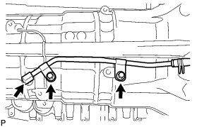
(a) Coat a new O-ring with ATF and install it to the breather tube.
(b) Install the breather tube with the 2 bolts.
Torque : 5.4 Nm (55 kgf-cm, 48 in-lbf)
74. INSTALL SPEED SENSOR
(a) Coat 2 new O-rings with ATF and install one to each speed sensor.
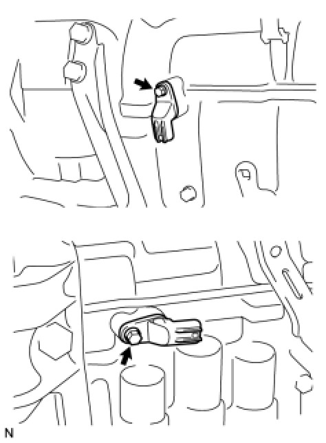
(b) Install the 2 speed sensors.
(c) Install the 2 bolts.
Torque : 5.4 Nm (55 kgf-cm, 48 in-lbf)
75. INSTALL OIL COOLER TUBE UNION
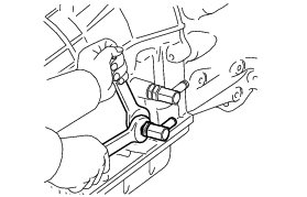
(a) Coat 2 new O-rings with ATF and install them to the 2 oil cooler tube unions.
(b) Install the 2 oil cooler tube unions.
Torque : 29 Nm (300 kgf-cm, 22 ft-lbf)
76. INSTALL PARK/NEUTRAL POSITION SWITCH ASSEMBLY
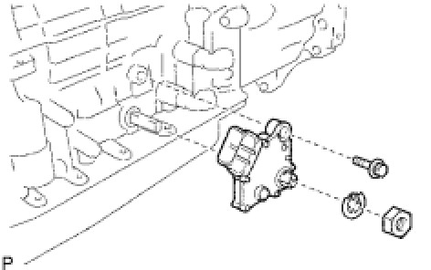
(a) Install the park/neutral position switch to the manual valve lever shaft and temporarily install the adjusting bolt.
(b) Install a new lock washer and the nut.
Torque : 6.9 Nm (70 kgf-cm, 61 in-lbf)
(c) Turn the control shaft lever counterclockwise until it stops, and then turn it clockwise 2 notches to set it to the N position.
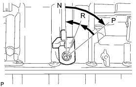
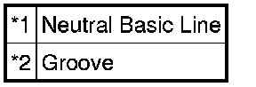
(d) Align the neutral basic line with the switch groove as shown in the illustration and tighten the adjusting bolt.
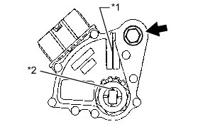
Torque : 13 Nm (130 kgf-cm, 9 ft-lbf)
Text in Illustration
(e) Using a screwdriver, bend the tabs of the lock washer.
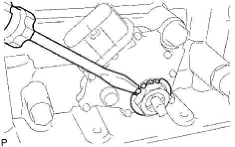
HINT
Bend at least 2 of the lock washer tabs.
77. INSTALL TRANSMISSION CONTROL SHAFT LEVER LH
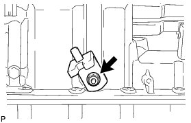
(a) Install the control shaft lever LH with the washer and nut.
Torque : 16 Nm (163 kgf-cm, 12 ft-lbf)