Part 3
A760F AUTOMATIC TRANSMISSION / TRANSAXLE: AUTOMATIC TRANSMISSION UNIT: REASSEMBLY
41. INSTALL FORWARD MULTIPLE DISC CLUTCH DISC SET
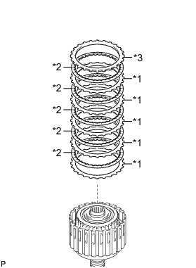
(a) Install the 5 plates, 5 discs and flange to the input shaft.
Install in order:
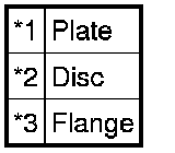
*1 - *2 - *1 - *2 - *1 - *2 - *1 - *2 - *1 - *2 - *3
Text in Illustration
NOTICE:
Before assembling new discs, soak them in ATF for at least 2 hours.
(b) Temporarily install the snap ring.
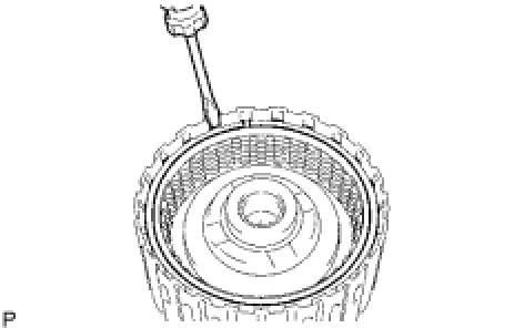
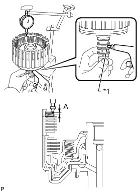
(c) Using a dial indicator, measure the moving distance (A) of the clutch flange at both ends across the diameter while applying compressed air (196 kPa, 2.0 kgf/cm2, 28 psi) into the oil hole as shown in the illustration.
Text in Illustration

Standard moving distance (A):
0.7 to 1.0 mm (0.0276 to 0.0394 in.)
If the moving distance (A) is not as specified, select a flange of an appropriate thickness from the table below so that the measured value is within the standard range.
Flange Thickness:
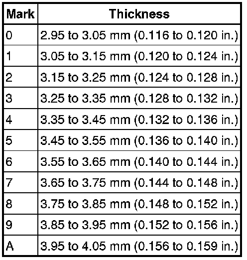
(d) Temporarily remove the snap ring, replace the flange with the selected flange and reinstall the snap ring.
42. INSTALL INPUT SHAFT OIL SEAL RING
(a) Coat 4 new oil seal rings with ATF.
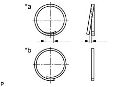
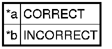
(b) Overlap the seal ring ends in the axial direction.
Text in Illustration
NOTICE:
* Overlapping the seal ring ends in the axial direction prevents damage to the seal ring.
* Do not overlap the seal ring ends in the radial direction, as this may damage the seal ring.
(c) Squeeze the ends of the 4 oil seal rings together, and then install them to the input shaft groove.
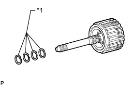
Text in Illustration

NOTICE:
Do not excessively widen the rings.
HINT
After installing the oil seal rings, check that they rotate smoothly.
43. INSTALL INPUT SHAFT ASSEMBLY
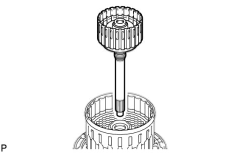
(a) Install the input shaft to the clutch drum.
44. INSTALL FORWARD CLUTCH HUB SUB-ASSEMBLY
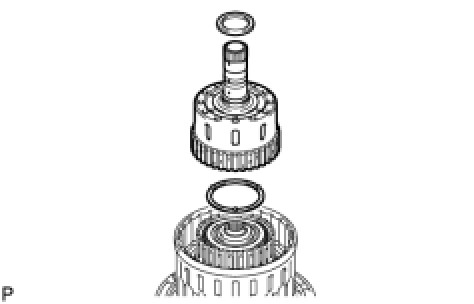
(a) Install the No. 3 clutch hub thrust washer, forward clutch hub and thrust needle roller bearing to the clutch drum.
NOTICE:
Before installing the forward clutch hub, apply ATF to the forward clutch hub bush sliding surfaces. After the installation, check that the forward clutch hub rotates smoothly.
HINT
Use a small amount of MP grease to make the thrust needle roller bearing and thrust washer stay securely in place.
Bearing Diameter:

45. INSTALL REVERSE CLUTCH HUB SUB-ASSEMBLY
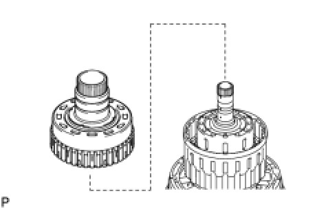
(a) Install the reverse clutch hub to the clutch drum.
NOTICE:
Before installing the reverse clutch hub, apply ATF to the reverse clutch hub bush sliding surfaces. After the installation, check that the reverse clutch rotates smoothly.
46. INSTALL REAR CLUTCH DISC SET
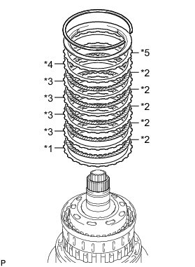
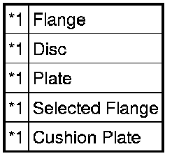
(a) Install the flange, 5 discs, 4 plates, selected flange, cushion plate and reverse clutch reaction sleeve to the clutch drum.
Install in order:
*1 - *2 - *3 - *2 - *3 - *2 - *3 - *2 - *3 - *2 - *4 - *5
Text in Illustration
(b) Using a screwdriver, install the snap ring to the clutch drum.
47. INSTALL NO. 2 1-WAY CLUTCH ASSEMBLY
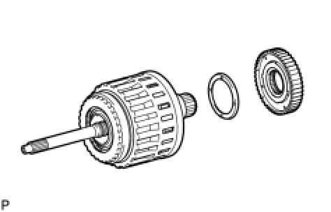
(a) Install the clutch drum thrust washer to the clutch drum.
HINT
Use a small amount of MP grease to make the thrust washer stay securely in place.
(b) Install the 1-way clutch to the clutch drum.
48. INSPECT NO. 2 1-WAY CLUTCH ASSEMBLY Transmission Unit
49. INSTALL CLUTCH DRUM AND INPUT SHAFT ASSEMBLY
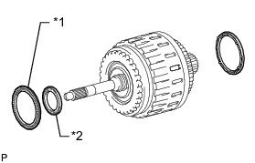
(a) Install the 2 thrust needle roller bearings.
HINT
Use a small amount of MP grease to make the thrust needle roller bearings stay securely in place.
Bearing Diameter:

Text in Illustration
(b) Coat the clutch drum thrust washer with petroleum jelly and install it to the clutch drum and input shaft assembly.
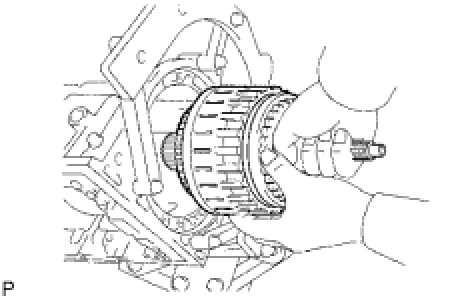
(c) Install the clutch drum and input shaft assembly to the transmission case.
50. INSTALL OIL PUMP ASSEMBLY
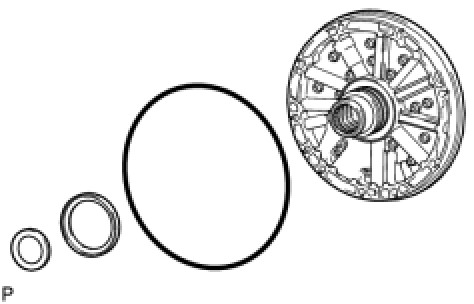
(a) Coat a new O-ring with ATF and install it to the oil pump.
(b) Install the 2 thrust bearing races to the front oil pump.
Thrust Bearing Race Diameter:

(c) Pass the input shaft through the center hole of the oil pump and align the bolt holes of the oil pump assembly with the transmission case.
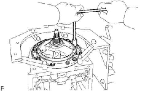
(d) Hold the input shaft and lightly press the oil pump body to slide the oil seal rings into the overdrive direct clutch drum.
(e) Apply seal packing to the flanges of the bolts.
Seal packing:
Toyota Genuine Seal Packing 1281,
Three Bond 1281 or equivalent
(f) Install the oil pump with the 10 bolts.
Torque : 21 Nm (215 kgf-cm, 16 ft-lbf)
NOTICE:
During installation, do not allow oil to contact the bolts or the surface of the oil pump body.
51. INSPECT INDIVIDUAL PISTON OPERATION Transmission Unit
52. INSTALL MANUAL VALVE LEVER SHAFT OIL SEAL
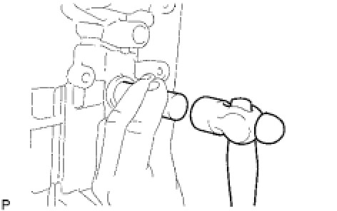
(a) Using SST, tap in 2 new oil seals.
SST : 09350-30020
09350-07110
Standard depth:
-0.3 to 0.3 mm (-0.0118 to 0.0118 in.)
(b) Coat the lips of the oil seals with MP grease.
53. INSTALL MANUAL VALVE LEVER SUB-ASSEMBLY
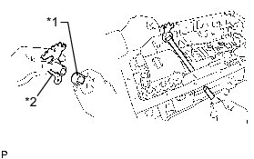
(a) Install a new spacer to the manual valve lever.
Text in Illustration
(b) Push the manual valve lever shaft through the transmission case and install the manual valve lever to the shaft.
(c) Using a hammer, tap in a new spring pin.
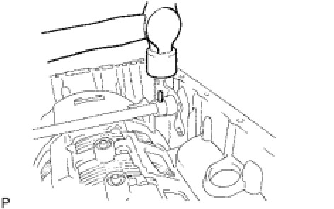
(d) Align the manual valve lever indentation with the spacer hole and stake them together with a punch.
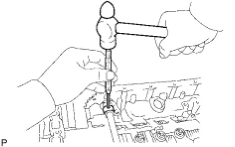
(e) Check that the shaft rotates smoothly.
54. INSTALL PARKING LOCK PAWL SHAFT
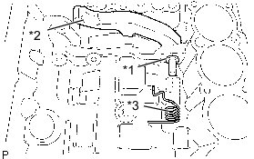
(a) Install a new E-ring to the shaft.
Text in Illustration
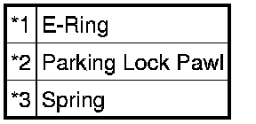
(b) Install the parking lock pawl, shaft and spring.
55. INSTALL PARKING LOCK ROD SUB-ASSEMBLY
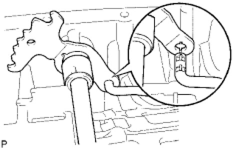
(a) Connect the parking lock rod to the manual valve lever.
56. INSTALL PARKING LOCK PAWL BRACKET
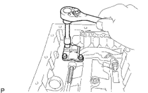
(a) Install the parking lock pawl bracket to the transmission case with the 3 bolts.
Torque : 7.4 Nm (75 kgf-cm, 65 in-lbf)
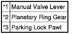
(b) Move the manual valve lever to the P position and confirm that the planetary ring gear is correctly locked by the lock pawl.
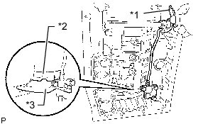
Text in Illustration
57. INSTALL B-1 ACCUMULATOR VALVE
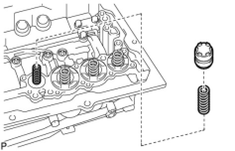
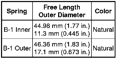
(a) Install the 2 springs and accumulator valve to the hole.
Spring Diameter:
58. INSTALL C-3 ACCUMULATOR PISTON
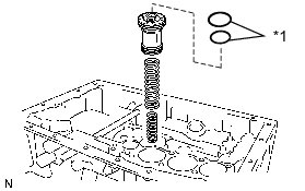
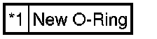
(a) Coat 2 new O-rings with ATF and install them to the piston.
Text in Illustration
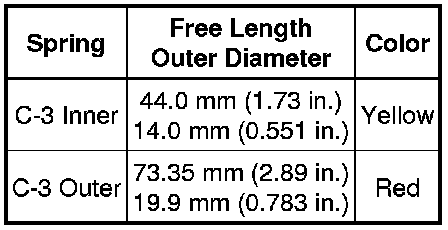
(b) Install the 2 springs and accumulator piston to the hole.
Spring Diameter:
59. INSTALL B-3 ACCUMULATOR PISTON
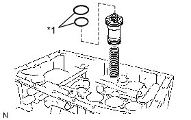
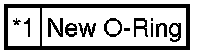
(a) Coat 2 new O-rings with ATF and install them to the piston.
Text in Illustration
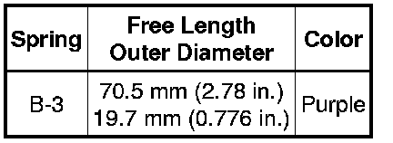
(b) Install the spring and accumulator piston to the hole.
Spring Diameter:
60. INSTALL C-2 ACCUMULATOR PISTON
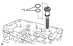
(a) Coat 2 new O-rings with ATF and install them to the piston.
Text in Illustration
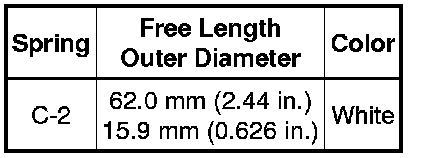
(b) Install the spring and accumulator piston to the hole.
Spring Diameter:
61. INSTALL CHECK BALL BODY
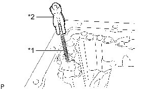
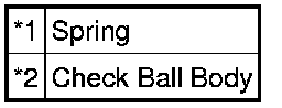
(a) Install the spring and check ball body.
Text in Illustration
62. INSTALL BRAKE DRUM GASKET
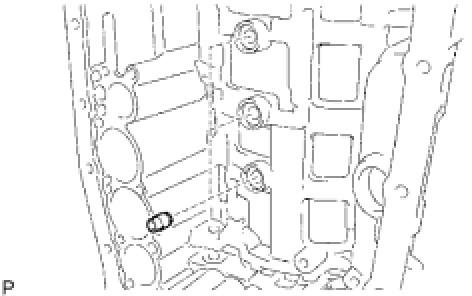
(a) Install 3 new brake drum gaskets.
63. INSTALL TRANSMISSION CASE GASKET
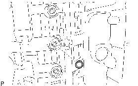
(a) Install 3 new transmission case gaskets.
64. INSTALL TRANSMISSION VALVE BODY ASSEMBLY
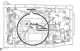
(a) Align the hole of the manual valve with the pin of the lever and connect the pin to the manual valve.
Text in Illustration

(b) Install the valve body with the 19 bolts.
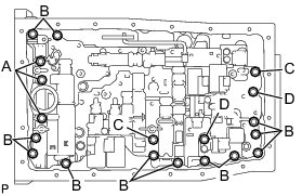
Torque : 11 Nm (112 kgf-cm, 8 ft-lbf)
HINT
Each bolt length is indicated below.
36 mm (1.42 in.) for bolt A
25 mm (0.984 in.) for bolt B
45 mm (1.77 in.) for bolt C
50 mm (1.97 in.) for bolt D
(c) Install the detent spring and detent spring cover with the bolt.
Torque : 10 Nm (102 kgf-cm, 7 ft-lbf)
65. INSTALL TRANSMISSION WIRE
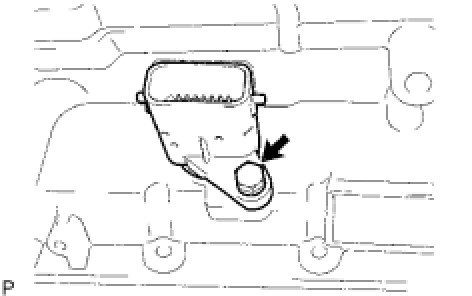
(a) Coat a new O-ring with ATF, and install it to the transmission wire connector.
(b) Install the transmission wire.
(c) Install the bolt.
Torque : 5.4 Nm (55 kgf-cm, 48 in-lbf)
(d) Connect the 9 solenoid connectors.
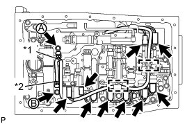
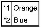
(e) Connect the 2 ATF temperature sensors with the 2 clamps and 2 bolts.
for bolt A - Torque : 10 Nm (102 kgf-cm, 7 ft-lbf)
for bolt B - Torque : 11 Nm (112 kgf-cm, 8 ft-lbf)
Text in Illustration
HINT
Each bolt length is indicated below.
12 mm (0.472 in.) for bolt A
36 mm (1.42 in.) for bolt B
(f) Attach the wire harness to the 2 clamps.
66. INSTALL VALVE BODY OIL STRAINER ASSEMBLY
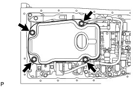
(a) Coat a new O-ring with ATF and install it to the oil strainer.
(b) Install the oil strainer with the 4 bolts.
Torque : 10 Nm (102 kgf-cm, 7 ft-lbf)
67. INSTALL TRANSMISSION OIL CLEANER MAGNET
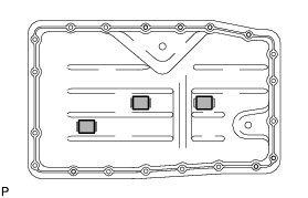
(a) Install the 4 magnets.
68. INSTALL AUTOMATIC TRANSMISSION OIL PAN SUB-ASSEMBLY
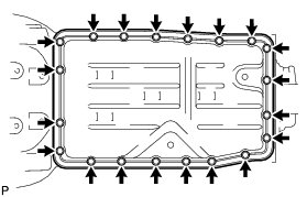
(a) Install a new gasket to the oil pan.
(b) Install the oil pan with the 20 bolts.
Torque : 7.0 Nm (71 kgf-cm, 62 in-lbf)
(c) Install a new gasket and the drain plug.
Torque : 20 Nm (204 kgf-cm, 15 ft-lbf)
69. INSTALL TRANSFER CASE REAR ADAPTER OIL RECEIVER
(a) Install the transfer case rear adaptor oil receiver to the rear adaptor transfer.
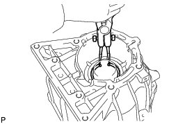
(b) Using snap ring pliers, install the snap ring.
70. INSTALL EXTENSION HOUSING REAR OIL SEAL
(a) Coat the lip of a new oil seal with ATF.
(b) Using SST and a hammer, tap in the oil seal.
SST : 09950-60010
09951-00650
SST : 09950-70010
09951-07150
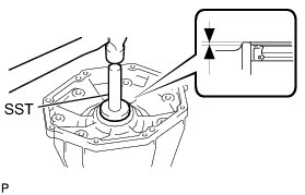
Standard depth:
0 to 0.5 mm (0 to 0.0197 in.)