Part 1
A760F AUTOMATIC TRANSMISSION / TRANSAXLE: AUTOMATIC TRANSMISSION UNIT: REASSEMBLY
1. BEARING POSITION
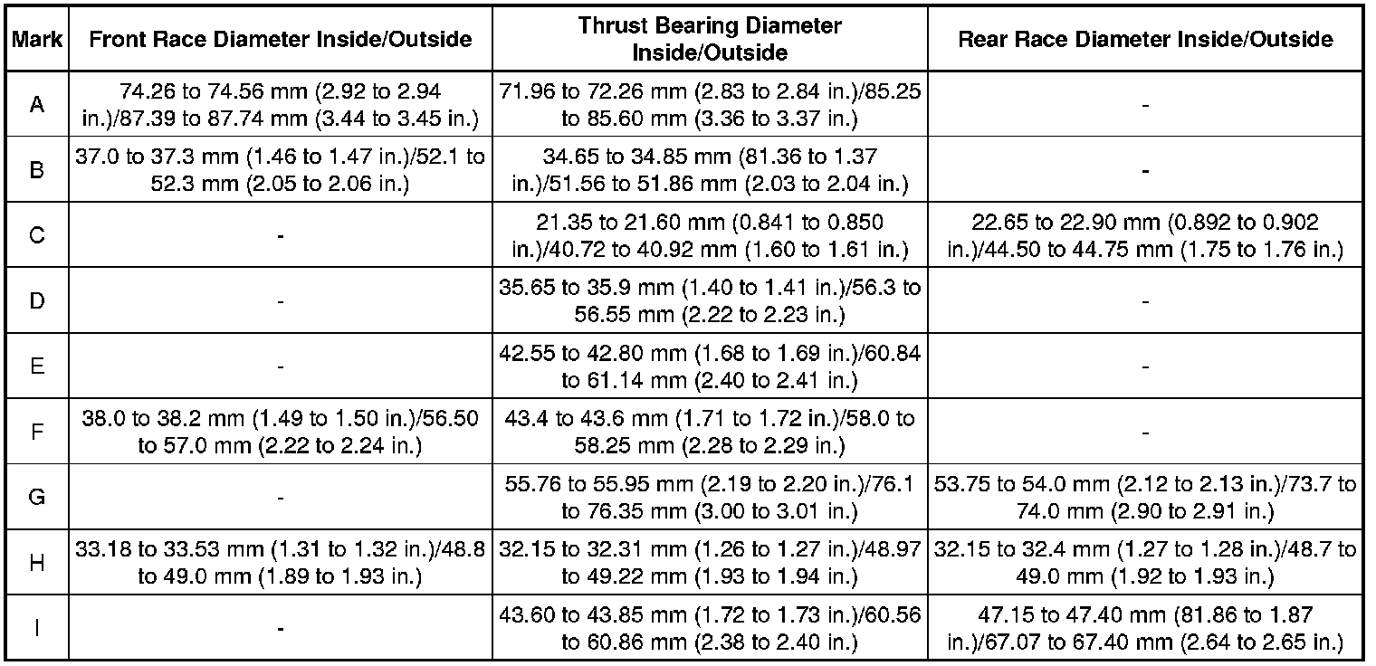
(a) Check the bearing positions.
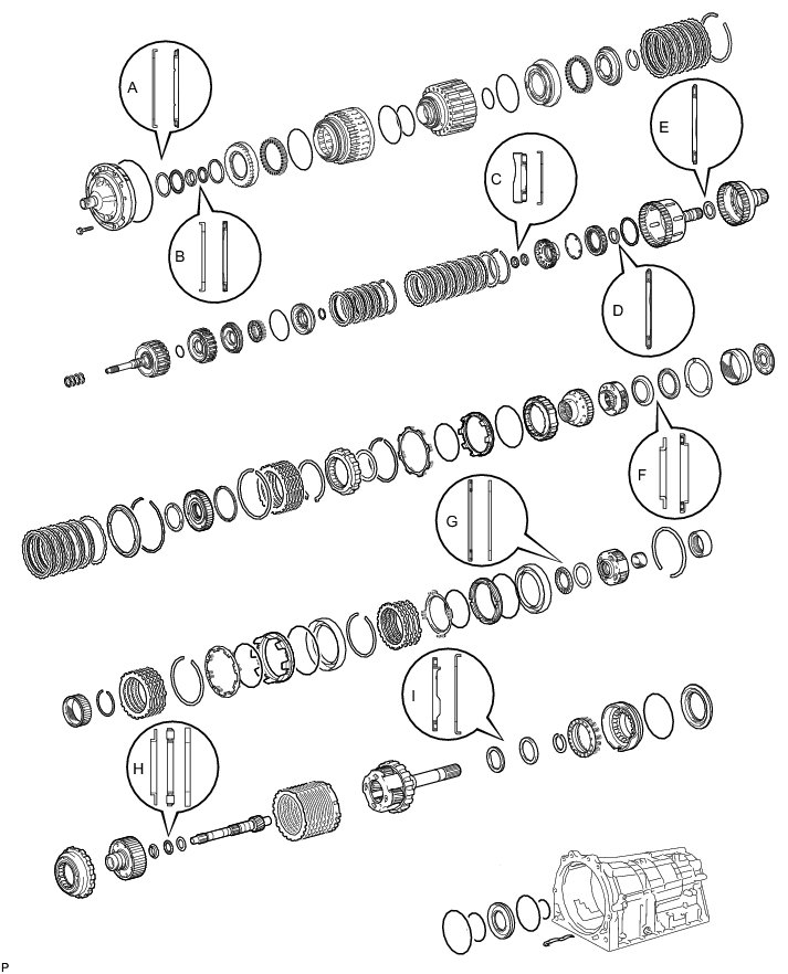
Bearing Diameter:
2. ASSEMBLE NO. 4 BRAKE PISTON AND BRAKE REACTION SLEEVE
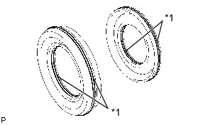
(a) Coat 2 new O-rings with ATF and install them to the brake reaction sleeve.
(b) Coat 2 new O-rings with ATF and install them to the No. 4 brake piston.
Text in Illustration
(c) Install the No. 4 brake piston to the reaction sleeve.
3. INSTALL NO. 4 BRAKE PISTON WITH BRAKE REACTION SLEEVE
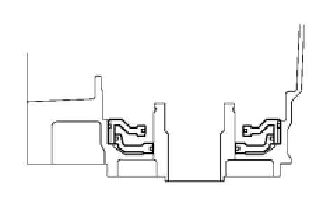
(a) Install the No. 4 brake piston with brake reaction sleeve to the transmission case
NOTICE:
* Do not damage the O-rings.
* Make sure the No. 4 brake piston is underneath the brake reaction sleeve.
4. INSTALL 1ST AND REVERSE BRAKE PISTON
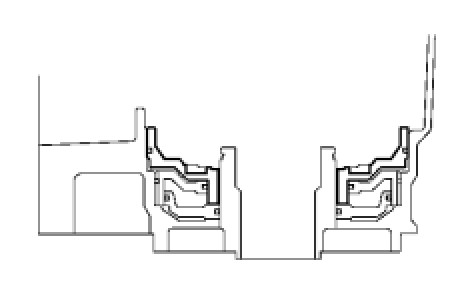
(a) Coat a new O-ring with ATF.
(b) Install the O-ring to the 1st and reverse brake piston.
(c) With the spring seat of the piston facing upwards (the front side), install the piston to the transmission case.
NOTICE:
Be careful not to damage the O-ring.
5. INSTALL 1ST AND REVERSE BRAKE RETURN SPRING SUB-ASSEMBLY
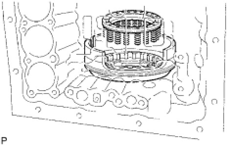
(a) Place the brake return spring onto the 1st and reverse brake piston.
(b) Place SST on the spring retainer and compress the return spring.
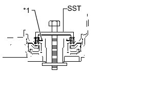
SST : 09350-30020
09350-07050
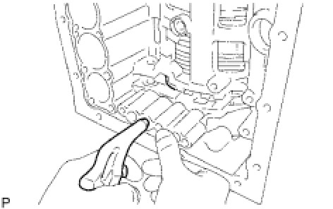
(c) Using SST, install the snap ring.
SST : 09350-30020
09350-07070
Text in Illustration
NOTICE:
Make sure the end gap of the snap ring is not aligned with the spring retainer claw.
(d) Make sure the No. 4 brake piston moves smoothly when applying and releasing compressed air into and from the transmission case.
6. INSTALL REAR PLANETARY GEAR ASSEMBLY
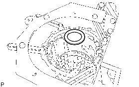
(a) Install the thrust bearing race.
Bearing Race Diameter:

(b) Install the thrust needle roller bearing to the rear planetary gear.
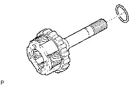
Bearing Diameter:

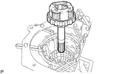
(c) Install the rear planetary gear assembly.
7. SELECT NO. 4 BRAKE FLANGE
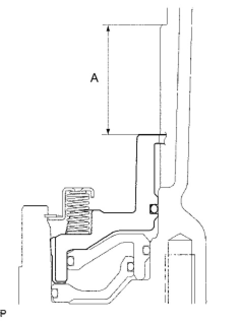
(a) Using a vernier caliper, measure distance A (from the top surface of the 1st and reverse brake piston to the step in the transmission case) in the illustration.
NOTICE:
The 1st and reverse brake piston must be installed securely to the end face of the transmission case.
HINT
Distance A = 36.35 to 37.09 mm (1.43 to 1.46 in.)
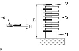
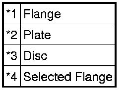
(b) Assemble the flange, 8 discs and 7 plates, and then, using a vernier caliper, measure distance B in the illustration at both ends across the diameter and calculate the average.
Text in Illustration
HINT
Distance B = 33.94 to 35.04 mm (1.34 to 1.38 in.)
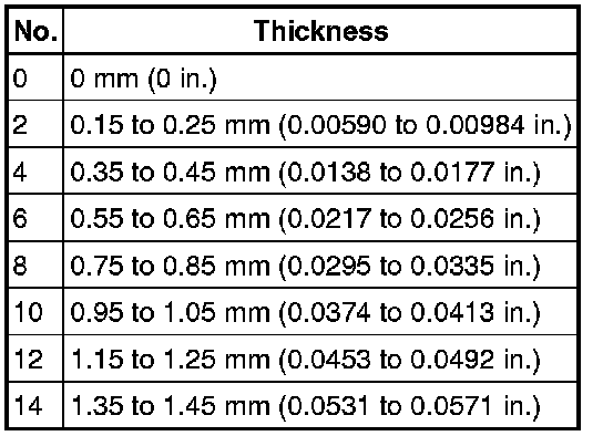
(c) Select a No. 4 brake flange so that the value of measured distance A minus distance B minus thickness H is 1.35 to 1.65 mm (0.0531 to 0.0650 in.).
Thickness H:
8. INSTALL NO. 4 BRAKE DISC
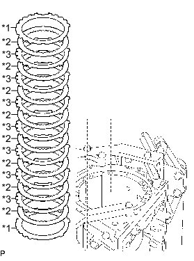
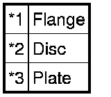
(a) Install the flange, 8 discs, 7 plates and selected flange.
Install in order:
*1 - *2 - *3 - *2 - *3 - *2 - *3 - *2 - *3 - *2 - *3 - *2 - *3 - *2 - *3 - *2 - *1
Text in Illustration
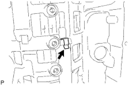
9. INSTALL BRAKE PLATE STOPPER SPRING
10. INSTALL REAR PLANETARY RING GEAR FLANGE SUB-ASSEMBLY
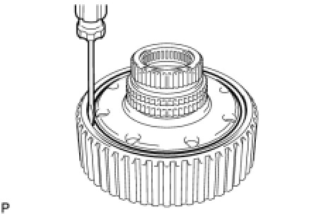
(a) Install the rear planetary ring gear flange to the rear planetary ring gear.
(b) Using a screwdriver, install the snap ring.
(c) Install the thrust bearing race, thrust needle roller bearing, thrust bearing race and planetary ring gear flange together with the rear planetary ring gear to the intermediate shaft.
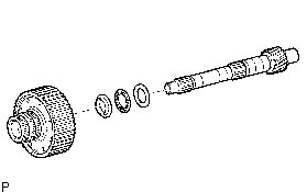
Bearing and Race Diameter:

11. INSTALL NO. 3 1-WAY CLUTCH ASSEMBLY
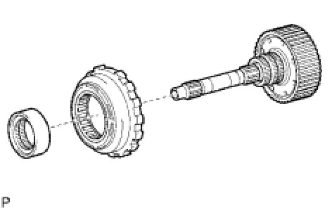
(a) Install the 1-way clutch and 1-way clutch inner race to the intermediate shaft.
12. INSTALL INTERMEDIATE SHAFT
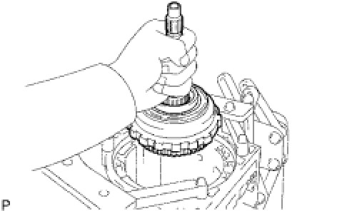
(a) Install the intermediate shaft with No. 3 1-way clutch assembly to the case.
(b) Using SST, install the snap ring.
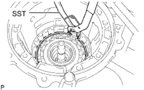
SST : 09350-30020
09350-07060
13. INSTALL CENTER PLANETARY GEAR ASSEMBLY
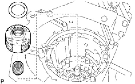
(a) Install the planetary sun gear and center planetary gear to the case.
(b) Coat the thrust bearing race with petroleum jelly and install it to the center planetary gear.
Race Diameter:

14. INSTALL NO. 2 BRAKE PISTON
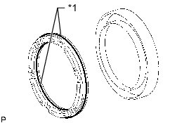
(a) Coat 2 new O-rings with ATF and install them to the brake piston.
Text in Illustration
(b) Press the brake piston into the brake cylinder with both hands.
NOTICE:
Be careful not to damage the O-rings.
(c) Install the No. 2 brake cylinder with No. 2 brake piston to the case.
HINT
Install the No. 2 brake cylinder so that the projection faces the top of the transmission case.
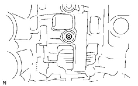
(d) Check that the oil pressure apply hole of the No. 2 brake cylinder aligns with the oil pressure apply hole of the transmission case.
15. SELECT NO. 2 BRAKE FLANGE
(a) Install the No. 2 brake piston return spring and flange to the No. 2 brake piston.
(b) Place SST on the brake flange and compress the brake return spring.
SST : 09351-40010
09351-04010
09351-04020
09351-04040
09351-04050
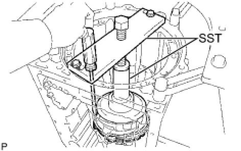
(c) Using a screwdriver, install the snap ring to the transmission case.
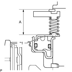
(d) Measure distance A (from the top surface of the snap ring to the surface of the brake piston return spring retainer) in the illustration.
Text in Illustration

HINT
Standard distance A: 20.94 to 22.12 mm (0.824 to 0.871 in.)
(e) Remove the snap ring, flange and No. 2 brake piston return spring.
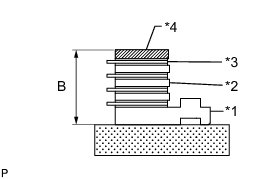
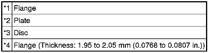
(f) Assemble the flange, 4 discs, 3 plates and flange (thickness: 1.95 to 2.05 mm (0.0768 to 0.0807 in.)) as shown in the illustration, and then, using a vernier caliper, measure distance B in the illustration at both ends across the diameter and calculate the average.
Text in Illustration
HINT
Standard distance B: 18.52 to 19.15 mm (0.729 to 0.754 in.)
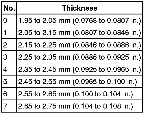
(g) Select a No. 2 brake flange so that the value of measured distance A minus distance B is 0.6 to 0.9 mm (0.0236 to 0.0354 in.).
Flange Thickness:
16. INSTALL NO. 2 BRAKE DISC SET
(a) Install the brake piston return spring.
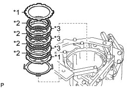
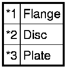
(b) Install the 2 flanges, 4 discs and 3 plates.
Install in order:
*1 - *2 - *3 - *2 - *3 - *2 - *3 - *2 - *1
Text in Illustration
(c) Using SST and a press, compress the return spring and install the snap ring.
SST : 09351-40010
09351-04010
09351-04030
09351-04040
09351-04050
17. INSTALL NO. 1 BRAKE PISTON
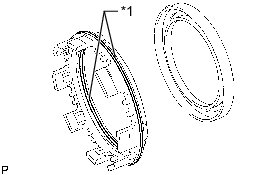
(a) Coat 2 new O-rings with ATF and install them to the brake piston.
Text in Illustration
(b) Press the brake piston into the brake cylinder with both hands to install it.
NOTICE:
Be careful not to damage the O-rings.
18. INSTALL NO. 1 BRAKE PISTON RETURN SPRING SUB-ASSEMBLY
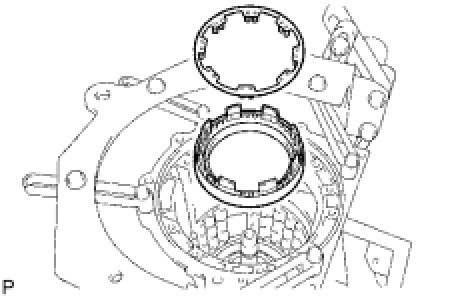
(a) Install the No. 1 brake cylinder with No. 1 brake piston and the brake piston return spring to the transmission case.
(b) Check that the oil pressure apply hole of the No. 1 brake cylinder aligns with the oil pressure apply hole of the transmission case.
19. INSTALL NO. 1 BRAKE PISTON RETURN SPRING SNAP RING
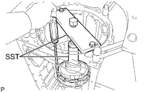
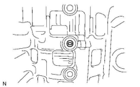
(a) Using SST, compress the return spring and install the No. 1 brake piston return spring snap ring.
SST : 09351-40010
09351-04010
09351-04030
09351-04040
09351-04050
20. SELECT NO. 1 BRAKE FLANGE
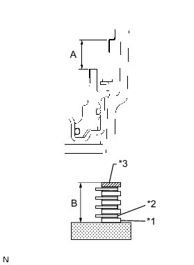
(a) Using a vernier caliper, measure distance A (from the step in the transmission case to the top surface of the No. 1 brake piston) in the illustration.
HINT
Standard distance A: 19.74 to 20.22 mm (0.777 to 0.796 in.)
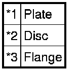
(b) Assemble the 4 plates, 4 discs and flange (thickness: 2.15 to 2.25 mm (0.0846 to 0.0886 in.)) as shown in the illustration, and then, using a vernier caliper, measure distance B in the illustration at both ends across the diameter and calculate the average.
Text in Illustration
HINT
Standard distance B: 18.93 to 19.39 mm (0.745 to 0.763 in.)
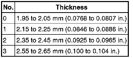
(c) Select a No. 1 brake flange so that the value of measured distance A minus distance B is 0.56 to 0.86 mm (0.0220 to 0.0339 in.).
Flange Thickness:
21. INSTALL NO. 1 BRAKE DISC
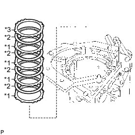
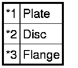
(a) Install the 4 plates, 4 discs and flange.
Install in order:
*1 - *2 - *1 - *2 - *1 - *2 - *1 - *2 - *3
Text in Illustration
22. INSTALL CENTER PLANETARY RING GEAR
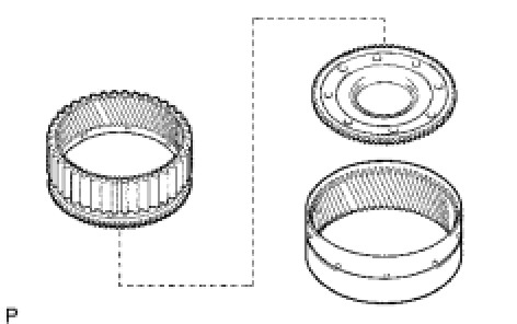
(a) Install the center planetary ring gear and front planetary ring gear flange to the front planetary ring gear.
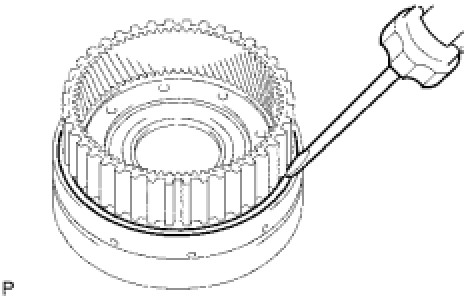
(b) Using a screwdriver, install the snap ring.
23. INSTALL FRONT PLANETARY RING GEAR
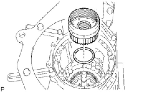
(a) Install the thrust needle roller bearing and front planetary ring gear to the case.
Thrust Needle Roller Bearing Diameter:

24. INSTALL FRONT PLANETARY GEAR ASSEMBLY
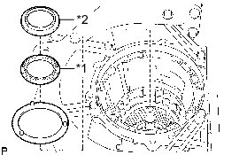
(a) Install the thrust washer and thrust needle roller bearing.
(b) Coat the thrust bearing race with petroleum jelly and install it to the front planetary ring gear.
Thrust Needle Roller Bearing and Race Diameter:

Text in Illustration
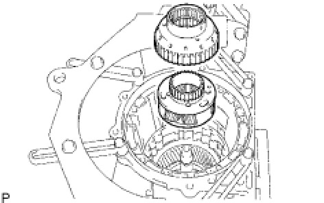
(c) Install the front planetary gear assembly and 1-way clutch inner race to the case.
25. INSTALL NO. 3 BRAKE PISTON
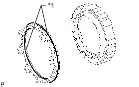
(a) Coat 2 new O-rings with ATF and install them to the No. 3 brake piston.
Text in Illustration
(b) Press the No. 3 brake cylinder into the No. 3 brake piston with both hands to install it.
NOTICE:
Be careful not to damage the O-rings.
(c) Using SST and a press, compress the return spring and install the snap ring.
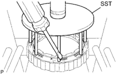
SST : 09351-40010
NOTICE:
Make sure the end gap of the snap ring is not aligned with the spring retainer claw.