Installation
FRONT SUSPENSION: FRONT STABILIZER BAR: INSTALLATION
1. TEMPORARILY INSTALL FRONT STABILIZER LINK ASSEMBLY RH
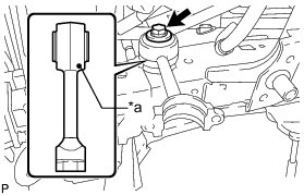
(a) Temporarily install the front stabilizer link assembly and spacer with the bolt.
HINT
Make sure that the identification mark on the front stabilizer link assembly faces inward and toward the front of the vehicle.
Text in Illustration
2. TEMPORARILY INSTALL FRONT STABILIZER WITH TUBE CYLINDER ASSEMBLY
(a) Install the 2 bleeder plug caps to the front stabilizer cylinder with tube cylinder assembly.
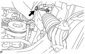
(b) Temporarily install the front stabilizer with tube cylinder assembly with the nut and bolt.
HINT
Pass the tube side of the front stabilizer with tube cylinder assembly under the return tube sub-assembly before installing it.
NOTICE:
* Turn the bolt while holding the nut.
* Do not hold the front stabilizer with tube cylinder assembly by the cylinder boot.
3. CONNECT NO. 1 FRONT STABILIZER CONTROL TUBE ASSEMBLY
(a) Apply suspension fluid to the threads of the flare nuts.
(b) Using a union nut wrench, connect the No. 1 front stabilizer control tube to the front stabilizer with tube cylinder assembly and tighten the flare nuts.
Torque : 44 Nm (450 kgf-cm, 33 ft-lbf)
HINT
Use the formula to calculate special torque values for situations where a union nut wrench is combined with a torque wrench Service Precautions.
(c) Tighten the bolt.
Torque : 29 Nm (296 kgf-cm, 21 ft-lbf)
4. INSTALL FRAME APRON SEAL BRACKET
(a) Install the bracket with the bolt.
Torque : 29 Nm (296 kgf-cm, 21 ft-lbf)
5. INSTALL FRONT STABILIZER BAR
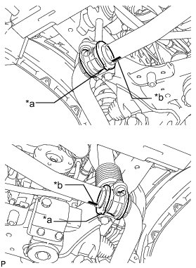
(a) Install the 2 front stabilizer lower bracket bushes to the front stabilizer bar.
HINT
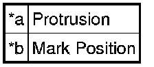
Align the protrusions on the bushes with the identification marks on the front stabilizer bar with the protrusions facing inward.
Text in Illustration
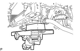
(b) With the identification marks of the front stabilizer bar facing downwards, support the front stabilizer bar with a jack.
NOTICE:
Place a wooden block between the jack and front stabilizer bar to prevent damage.
HINT
Place the jack under the center of the vehicle.
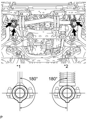
(c) Install the front stabilizer bar and 2 front stabilizer lower brackets with the 4 bolts.
Torque : 40 Nm (408 kgf-cm, 30 ft-lbf)
HINT
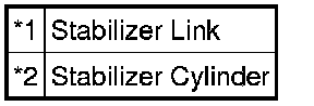
Make sure that the protrusions on the front stabilizer lower bracket bushes are positioned within 180° of the stabilizer cylinder and stabilizer link.
Text in Illustration
6. INSTALL FRONT STABILIZER END BRACKET
(a) Install the 2 front stabilizer brackets and 2 front stabilizer link bushes with the 4 bolts.
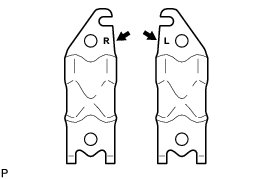
Torque : 75 Nm (765 kgf-cm, 55 ft-lbf)
HINT
There are stamps on the front stabilizer brackets to distinguish between the right and left brackets.
7. INSTALL FRONT SUSPENSION MEMBER BRACE SUB-ASSEMBLY
(a) Install the 2 member braces with the 6 bolts.
Torque : 30 Nm (306 kgf-cm, 22 ft-lbf)
8. BLEED SUSPENSION FLUID
(a) Bleed the suspension fluid Service and Repair.
9. INSTALL FRONT WHEEL
Torque : 112 Nm (1142 kgf-cm, 83 ft-lbf)
10. TIGHTEN FRONT STABILIZER LINK ASSEMBLY RH
(a) Tighten the bolt on the front stabilizer link assembly.
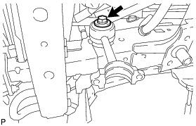
Torque : 140 Nm (1428 kgf-cm, 103 ft-lbf)
NOTICE:
Tighten the bolt with the wheels on the ground.
11. TIGHTEN FRONT STABILIZER WITH TUBE CYLINDER ASSEMBLY
(a) Tighten the bolt on the front stabilizer with tube cylinder assembly.
Torque : 130 Nm (1326 kgf-cm, 96 ft-lbf)
NOTICE:
Tighten the bolt with the wheels on the ground.
12. INSTALL FRONT FENDER APRON SEAL LH
(a) Install the front fender apron seal LH with the 7 clips.
13. INSTALL NO. 1 ENGINE UNDER COVER SUB-ASSEMBLY Installation
14. INSTALL LOWER FRONT BUMPER COVER Installation
15. INSTALL STABILIZER CONTROL VALVE PROTECTOR Installation
16. INSTALL SIDE STEP ASSEMBLY LH Installation
17. INSPECT VEHICLE HEIGHT
(a) Inspect the vehicle height Suspension Control System (w/ KDSS).