Reassembly
STEERING GEAR / LINKAGE: STEERING GEAR: REASSEMBLY
1. INSTALL STEERING RACK END SUB-ASSEMBLY
(a) Temporarily install the 2 steering rack ends to the steering rack.
(b) Fill up the ball joints of the steering rack ends with MP grease.
(c) Using SST, install the steering rack end (RH side) to the steering rack.
SST : 09922-10010
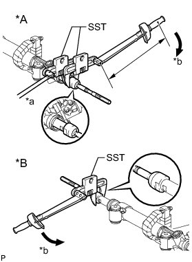
without SST - Torque : 105 Nm (1071 kgf-cm, 77 ft-lbf)
with SST - Torque : 77 Nm (784 kgf-cm, 57 ft-lbf)
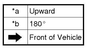
Text in Illustration
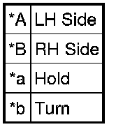
HINT
* Rotate SST in the direction shown in the illustration.
* Use a torque wrench with a fulcrum length of 400 mm (15.7 in.).
(d) Using SST and a wrench, install the steering rack end (LH side) to the steering rack.
SST : 09922-10010
without SST - Torque : 105 Nm (1071 kgf-cm, 77 ft-lbf)
with SST - Torque : 77 Nm (784 kgf-cm, 57 ft-lbf)
HINT
* Rotate SST in the direction shown in the illustration.
* Use a torque wrench with a fulcrum length of 400 mm (15.7 in.).
2. INSTALL NO. 2 STEERING RACK BOOT
(a) Apply silicon grease to the inside of the small opening of the boot.
(b) Install the 2 boots to the groove on the rack housing.
3. INSTALL NO. 1 STEERING RACK BOOT
HINT
Use the same procedures described for the No. 2 boot.
4. INSTALL STEERING RACK BOOT CLAMP RH
(a) Using SST, install a new boot clamp as shown in the illustration.
SST : 09521-24010
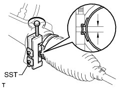
Standard clearance:
3.0 mm (0.118 in.) or less
NOTICE:
Be careful not to damage the boot.
5. INSTALL STEERING RACK BOOT CLAMP LH
HINT
Use the same procedures described for the RH side.
6. INSTALL STEERING RACK BOOT CLIP RH
(a) Using pliers, install the boot clip.
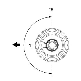
Text in Illustration
NOTICE:
Make sure that the claws of the clip are positioned within the area shown in the illustration.
7. INSTALL STEERING RACK BOOT CLIP LH
HINT
Use the same procedures described for the RH side.
8. INSTALL STEERING GEAR OUTLET RETURN TUBE
(a) Using a union nut wrench, install the return tube to the steering gear.
Torque : 25 Nm (255 kgf-cm, 18 ft-lbf)
HINT
Use the formula to calculate special torque values for situations where a union nut wrench is combined with a torque wrench Service Precautions.
9. INSTALL TURN PRESSURE TUBE
(a) Apply steering fluid to 2 new O-rings. Using a union nut wrench, install the 2 O-rings and turn pressure tube LH.
Torque : 13 Nm (127 kgf-cm, 9 ft-lbf)
HINT
Use the formula to calculate special torque values for situations where a union nut wrench is combined with a torque wrench Service Precautions.
(b) Apply steering fluid to 2 new O-rings. Using a union nut wrench, install the 2 O-rings and turn pressure tube RH.
Torque : 13 Nm (127 kgf-cm, 9 ft-lbf)
HINT
Use the formula to calculate special torque values for situations where a union nut wrench is combined with a torque wrench Service Precautions.
10. INSTALL TIE ROD END SUB-ASSEMBLY LH
(a) Align the matchmarks of the tie rod and rack end, and temporarily install the tie rod with the lock nut.
HINT
After adjusting toe-in, tighten the lock nut.
Torque : 88 Nm (897 kgf-cm, 65 ft-lbf)
11. INSTALL TIE ROD END SUB-ASSEMBLY RH
HINT
Use the same procedures described for the LH side.