Installation
1UR-FE EMISSION CONTROL: AIR SWITCHING VALVE (for Bank 2): INSTALLATION
1. INSTALL AIR SWITCHING VALVE ASSEMBLY
(a) Install a new gasket and the air switching valve with the 3 bolts.
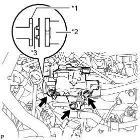
Torque : 24 Nm (245 kgf-cm, 18 ft-lbf)
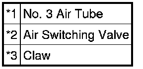
Text in Illustration
NOTICE:
Make sure the claws of the gasket are not caught between the air switching valve and No. 3 air tube.
(b) Install the 2 bolts.
Torque : 10 Nm (102 kgf-cm, 7 ft-lbf)
(c) Connect the wire harness clamp bracket with the bolt.
Torque : 8.0 Nm (82 kgf-cm, 71 in-lbf)
(d) Attach the wire harness clamp and connect the air switching valve connector.
2. CONNECT NO. 1 AIR INJECTION SYSTEM HOSE
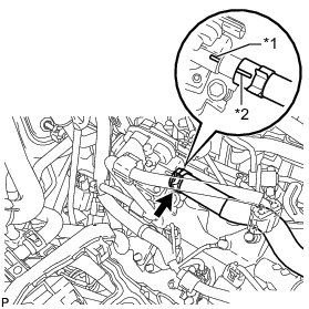
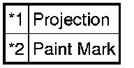
(a) Align the paint mark with the projection and connect the No. 1 air injection system hose.
Text in Illustration
HINT
Make sure the direction of the hose clamp is as shown in the illustration.
3. CONNECT NO. 3 VENTILATION HOSE
(a) Connect the No. 3 ventilation hose.
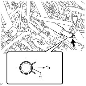
Text in Illustration
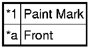
HINT
The direction of the hose clamp is indicated in the illustration.
4. INSTALL AIR CLEANER CAP AND HOSE Installation
5. INSTALL V-BANK COVER SUB-ASSEMBLY Installation
6. INSTALL ENGINE ROOM SIDE COVER Installation