Removal
METER / GAUGE / DISPLAY: COMBINATION METER: REMOVAL
1. DISABLE AUTO-AWAY/RETURN FUNCTION
(a) Disable the Auto-away/Return function by changing the customize parameter Programming and Relearning.
NOTICE:
Record the current customize parameter setting (whether the Auto-away/Return function is enabled or disabled) in order to restore the current setting after finishing the operation.
HINT
Performing the above operation causes the Auto-away/Return function to be disabled when the engine switch is turned off.
(b) Turn the engine switch on (IG). Operate the tilt and telescopic switch to fully extend and lower the steering column.
(c) Turn the engine switch off.
2. DISCONNECT CABLE FROM NEGATIVE BATTERY TERMINAL
NOTICE:
* w/ Navigation System:
After the engine switch is turned off, the display and navigation module display (navigation system) records various types of memory and settings. As a result, after turning the engine switch off, be sure to wait for the time specified in the following table before disconnecting the cable from the negative (-) battery terminal.
Waiting Time before Disconnecting Cable from Negative (-) Battery Terminal

* When disconnecting the cable, some systems need to be initialized after the cable is reconnected Repair Instruction - Initialization.
3. REMOVE LOWER STEERING COLUMN COVER (w/ Driver Monitor Camera)
4. REMOVE UPPER STEERING COLUMN COVER (w/ Driver Monitor Camera)
5. REMOVE NO. 2 SWITCH HOLE BASE Removal
6. REMOVE NO. 1 INSTRUMENT PANEL FINISH CUSHION Removal
7. REMOVE INSTRUMENT CLUSTER FINISH PANEL SUB-ASSEMBLY (w/o Driver Monitor Camera)
(a) Place protective tape as shown in the illustration.
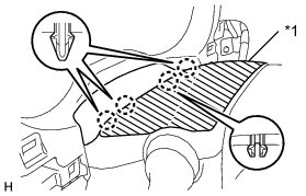
Text in Illustration

(b) Detach the 4 claws.
(c) Detach the 2 clips.
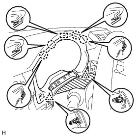
(d) Detach the 4 claws.
(e) Detach the guide and remove the instrument cluster finish panel sub-assembly.
8. REMOVE INSTRUMENT CLUSTER FINISH PANEL SUB-ASSEMBLY (w/ Driver Monitor Camera)
(a) Detach the 2 clips.
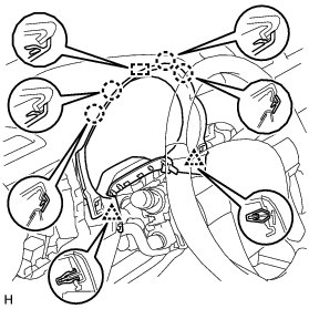
(b) Detach the 4 claws.
(c) Detach the guide and remove the instrument cluster finish panel sub-assembly.
9. REMOVE NO. 1 INSTRUMENT PANEL REGISTER ASSEMBLY Removal
10. REMOVE COMBINATION METER ASSEMBLY
(a) Remove the 2 screws.

Text in Illustration
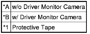
(b) Detach the 2 clips.
(c) Disconnect the connector and remove the combination meter assembly.