Removal
1UR-FE ENGINE MECHANICAL: CAMSHAFT: REMOVAL
1. REMOVE TIMING CHAIN COVER SUB-ASSEMBLY
(a) Remove the timing chain cover sub-assembly Removal.
2. SET NO. 1 CYLINDER TO TDC/COMPRESSION Disassembly
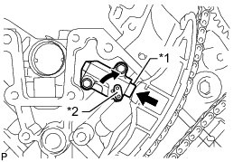
3. REMOVE NO. 1 CHAIN TENSIONER ASSEMBLY LH
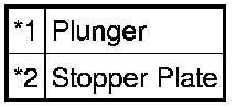
(a) Move the stopper plate upward to release the lock and push the plunger deep into the No. 1 chain tensioner.
Text in Illustration
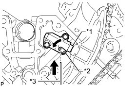
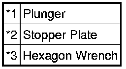
(b) Move the stopper plate downward to set the lock and insert a hexagon wrench into the stopper plate hole.
Text in Illustration
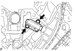
(c) Remove the 2 bolts, No. 1 chain tensioner LH and gasket.
4. REMOVE CHAIN TENSIONER SLIPPER LH
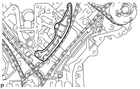
5. REMOVE NO. 1 CHAIN VIBRATION DAMPER LH
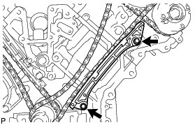
(a) Remove the 2 bolts and No. 1 chain vibration damper LH.
6. REMOVE NO. 1 CHAIN SUB-ASSEMBLY LH
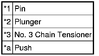
(a) While pushing down the No. 3 chain tensioner, insert a pin with a diameter of 1.0 mm (0.0394 in.) into the hole to fix the tensioner in place.
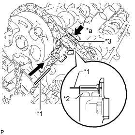
Text in Illustration
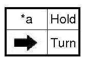
(b) Hold the hexagonal portion of the camshaft with a wrench and loosen the bolt.
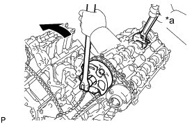
Text in Illustration
NOTICE:
* Be careful not to damage the cylinder head with the wrench.
* Do not disassemble the camshaft timing gear.
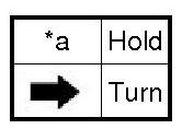
(c) Hold the hexagonal portion of the camshaft with a wrench and loosen the bolt.
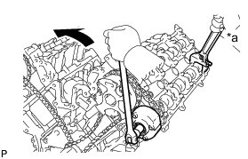
Text in Illustration
NOTICE:
* Be careful not to damage the cylinder head with the wrench.
* Do not disassemble the camshaft timing exhaust gear.
(d) Remove the 2 bolts. Then with the No. 1 and No. 2 chains still connected to the gears, remove the camshaft timing gear, camshaft timing exhaust gear and crankshaft timing sprocket LH.
(e) Remove the No. 1 and No. 2 chains from the gears.
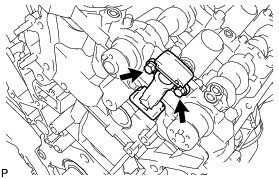
7. REMOVE NO. 3 CHAIN TENSIONER ASSEMBLY
(a) Remove the 2 bolts and No. 3 chain tensioner.
8. REMOVE NO. 1 CHAIN TENSIONER ASSEMBLY RH
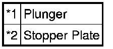
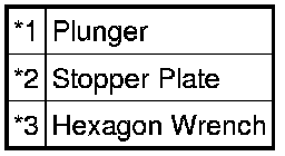
(a) Move the stopper plate upward to release the lock and push the plunger deep into the No. 1 chain tensioner.
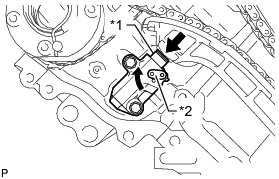
Text in Illustration
(b) Move the stopper plate downward to set the lock and insert a hexagon wrench into the stopper plate hole.
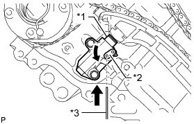
Text in Illustration
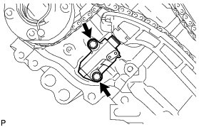
(c) Remove the 2 bolts and No. 1 chain tensioner RH.
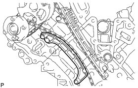
9. REMOVE CHAIN TENSIONER SLIPPER RH
10. REMOVE NO. 1 CHAIN VIBRATION DAMPER RH
(a) Remove the 2 bolts and No. 1 chain vibration damper RH.
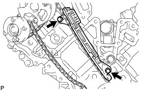
11. REMOVE NO. 1 CHAIN SUB-ASSEMBLY RH
(a) While raising up the No. 2 chain tensioner, insert a pin with a diameter of 1.0 mm (0.0394 in.) into the hole to fix the tensioner in place.
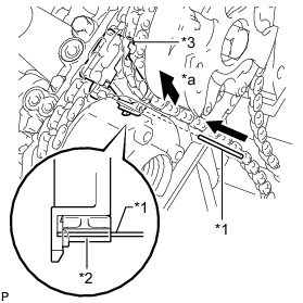
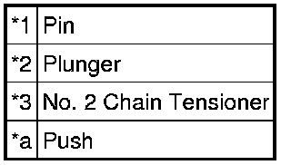
Text in Illustration
(b) Hold the hexagonal portion of the camshaft with a wrench and loosen the bolt.
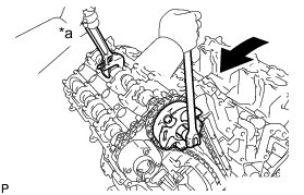
Text in Illustration
NOTICE:
* Be careful not to damage the cylinder head with the wrench.
* Do not disassemble the camshaft timing gear.
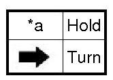
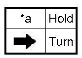
(c) Hold the hexagonal portion of the camshaft with a wrench and loosen the bolt.
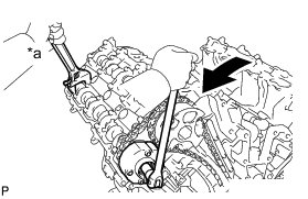
Text in Illustration
NOTICE:
* Be careful not to damage the cylinder head with the wrench.
* Do not disassemble the camshaft timing exhaust gear.
(d) Remove the 2 bolts. Then with the No. 1 and No. 2 chains still connected to the gears, remove the camshaft timing gear, camshaft timing exhaust gear and crankshaft timing sprocket RH.
(e) Remove the No. 1 and No. 2 chains from the gears.
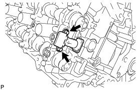
12. REMOVE NO. 2 CHAIN TENSIONER ASSEMBLY
(a) Remove the 2 bolts and No. 2 chain tensioner.
13. REMOVE CAMSHAFT BEARING CAP LH
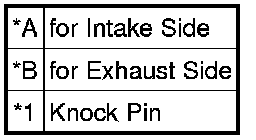
(a) Make sure that the knock pins of the camshafts are positioned as shown in the illustration.
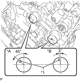
Text in Illustration
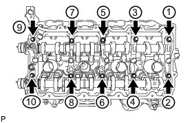
(b) Uniformly loosen and remove the 10 bearing cap bolts in the sequence shown in the illustration.
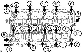
(c) Uniformly loosen and remove the 18 bearing cap bolts in the sequence shown in the illustration.
NOTICE:
Uniformly loosen the bolts while keeping the camshaft level.
(d) Remove the 6 camshaft bearing caps.
HINT
Arrange the removed parts in the correct order.
14. REMOVE NO. 3 CAMSHAFT SUB-ASSEMBLY
(a) Remove the No. 3 camshaft from the camshaft housing LH.
15. REMOVE NO. 4 CAMSHAFT SUB-ASSEMBLY
(a) Remove the No. 4 camshaft from the camshaft housing LH.
16. REMOVE CAMSHAFT HOUSING SUB-ASSEMBLY LH
(a) Remove the camshaft housing by prying between the cylinder head and camshaft housing with a screwdriver.
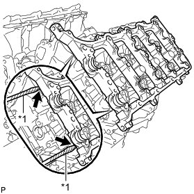
Text in Illustration

HINT
Tape the screwdriver tip before use.
NOTICE:
Be careful not to damage the contact surfaces of the cylinder head and camshaft housing.
17. REMOVE CAMSHAFT BEARING CAP RH
(a) Make sure that the knock pins of the camshafts are positioned as shown in the illustration.
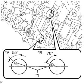
Text in Illustration
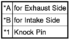
(b) Uniformly loosen and remove the 10 bearing cap bolts in the sequence shown in the illustration.
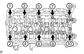
(c) Uniformly loosen and remove the 18 bearing cap bolts in the sequence shown in the illustration.

NOTICE:
Uniformly loosen the bolts while keeping the camshaft level.
(d) Remove the 6 camshaft bearing caps.
HINT
Arrange the removed parts in the correct order.
18. REMOVE NO. 1 CAMSHAFT SUB-ASSEMBLY
(a) Remove the No. 1 camshaft from the camshaft housing RH.
19. REMOVE NO. 2 CAMSHAFT SUB-ASSEMBLY
(a) Remove the No. 2 camshaft from the camshaft housing RH.
20. REMOVE CAMSHAFT HOUSING SUB-ASSEMBLY RH
(a) Remove the camshaft housing by prying between the cylinder head and camshaft housing with a screwdriver.
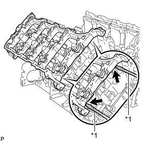
Text in Illustration

HINT
Tape the screwdriver tip before use.
NOTICE:
Be careful not to damage the contact surfaces of the cylinder head and camshaft housing.
21. INSPECT CAMSHAFT TIMING GEAR ASSEMBLY Engine Unit
22. INSPECT CAMSHAFT TIMING EXHAUST GEAR ASSEMBLY Engine Unit