Removal
BRAKE SYSTEM (OTHER): HYDRAULIC BRAKE BOOSTER: REMOVAL
HINT
When pressure in the power supply system is released, the reaction force decreases and the stroke becomes longer.
NOTICE:
* When installing, coat the parts indicated by arrows with lithium soap base glycol grease Components.
* Be sure not to allow the pump to contact the floor; support it with the booster body. If the pump contacts the floor, the red brake tube between the pump and booster body may be deformed, the operating sound of the pump may become loud enough to hear within the cabin, and fluid may leak.
* As high pressure is applied to the brake actuator tube No. 1, never deform it.
* Do not turn the engine switch on (IG) until the procedures are completed.
* Before starting the work, make sure that the engine switch is off and depress the brake pedal more than 20 times.
1. DISCONNECT CABLE FROM NEGATIVE BATTERY TERMINAL
CAUTION:
Wait at least 90 seconds after disconnecting the cable from the negative (-) battery terminal to disable the SRS system.
NOTICE:
* w/ Navigation System:
After the engine switch is turned off, the display and navigation module display (navigation system) records various types of memory and settings. As a result, after turning the engine switch off, be sure to wait for the time specified in the following table before disconnecting the cable from the negative (-) battery terminal.
Waiting Time before Disconnecting Cable from Negative (-) Battery Terminal:

* When disconnecting the cable, some systems need to be initialized after the cable is reconnected Repair Instruction - Initialization.
2. REMOVE ENGINE ROOM SIDE COVER LH
(a) Remove the 4 clips and engine room side cover LH.
3. DRAIN BRAKE FLUID
NOTICE:
Wash off brake fluid immediately if it comes into contact with a painted surface.
4. REMOVE LOWER NO. 1 INSTRUMENT PANEL AIRBAG ASSEMBLY
(a) Remove the lower No. 1 instrument panel airbag assembly Removal.
5. REMOVE PUSH ROD PIN
(a) Remove the clip and push rod pin from the brake pedal lever.
6. REMOVE AIR INJECTION CONTROL DRIVER WITH BRACKET Removal
7. REMOVE HYDRAULIC BRAKE BOOSTER ASSEMBLY
(a) Disconnect the 3 connectors from the hydraulic brake booster assembly.
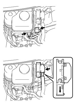
(b) Detach the clamp.
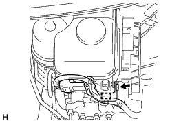
(c) Remove the bolt and wiring harness bracket.
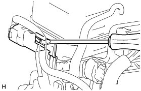
(d) Using a screwdriver, detach the VSC connector from the wiring harness bracket.
(e) Use tags or make a memo to identify the place to reconnect.
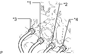
HINT
* *1: To front wheel cylinder RH
* *2: To front wheel cylinder LH
* *3: To rear wheel cylinder RH
* *4: To rear wheel cylinder LH
(f) Using a union nut wrench, disconnect the 4 brake lines from the hydraulic brake booster assembly.
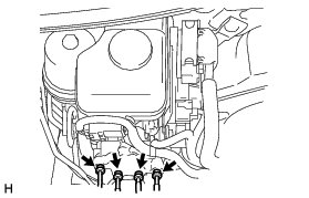
(g) Disconnect the 3 brake tubes from the clamp.
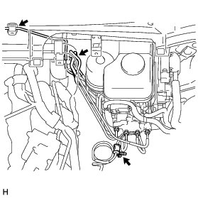
(h) Disconnect the brake tube from the clamp.
NOTICE:
* If excessive force is used when disconnecting the brake tube from the clamp, the clamp may brake.
* If the clamp breaks, do not reuse it. Replace the clamp with a new one.
(i) Remove the bolt and disconnect the clamp from the body.
(j) Remove the 4 nuts and pull out the hydraulic brake booster assembly.
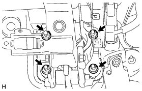
8. REMOVE BRAKE BOOSTER GASKET
(a) Remove the brake booster gasket from the brake master cylinder.