Part 1
AUDIO / VIDEO: AUDIO AND VISUAL SYSTEM (w/ Multi-display): Speaker Circuit
- Speaker Circuit
DESCRIPTION
The stereo component amplifier assembly sends sound signals to the speaker.
WIRING DIAGRAM
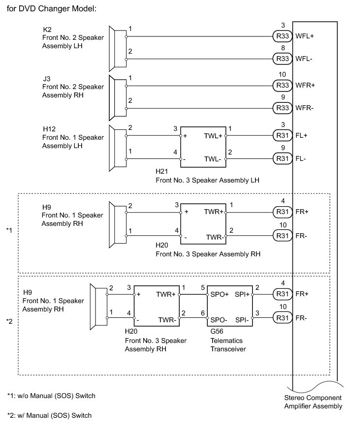
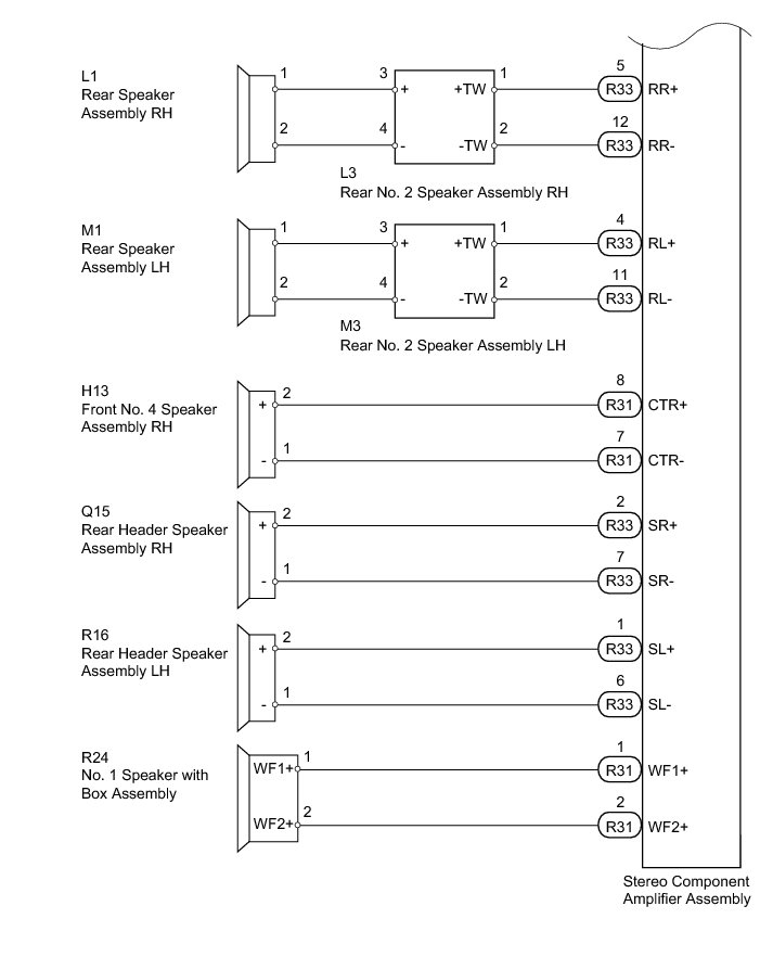
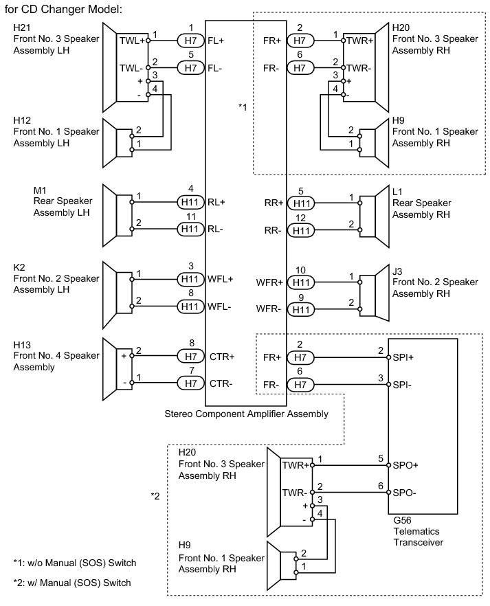
INSPECTION PROCEDURE
PROCEDURE
1. CHECK VEHICLE TYPE
(a) Check the vehicle type.
Result
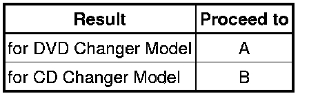
B -- CHECK SPEAKER
A -- Continue to next step.
2. CHECK SPEAKER
(a) Check which speakers are malfunctioning.
Result
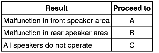
C -- REPLACE STEREO COMPONENT AMPLIFIER ASSEMBLY Removal
B -- CHECK REAR SIDE SPEAKER
A -- Continue to next step.
3. CHECK FRONT SIDE SPEAKER
(a) Check which speakers are malfunctioning.
Result
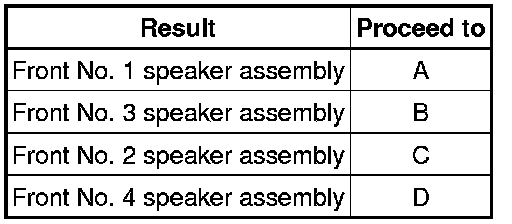
D -- INSPECT FRONT NO. 4 SPEAKER ASSEMBLY
C -- INSPECT FRONT NO. 2 SPEAKER ASSEMBLY
B -- REPLACE FRONT NO. 3 SPEAKER ASSEMBLY
A -- Continue to next step.
4. INSPECT FRONT NO. 1 SPEAKER ASSEMBLY
(a) Disconnect the H9*1 and/or H12*2 front No. 1 speaker assembly connector.
*1: for RH
*2: for LH
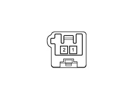
(b) Measure the resistance according to the value(s) in the table below.
Standard Resistance:

NG -- REPLACE FRONT NO. 1 SPEAKER ASSEMBLY Removal
OK -- Continue to next step.
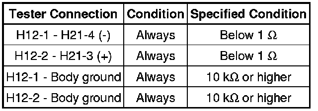
5. CHECK HARNESS AND CONNECTOR (FRONT NO. 1 SPEAKER - FRONT NO. 3 SPEAKER)
*1: for RH
*2: for LH
(a) Disconnect the H9*1 and/or H12*2 front No. 1 speaker assembly connector.
(b) Disconnect the H20*1 and/or H21*2 front No. 3 speaker assembly connector.
(c) Measure the resistance according to the value(s) in the table below.
Standard Resistance:
for RH
for LH
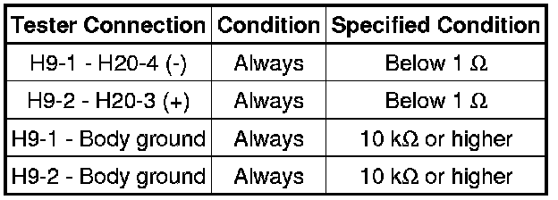
NG -- REPAIR OR REPLACE HARNESS OR CONNECTOR
OK -- Continue to next step.
6. INSPECT FRONT NO. 3 SPEAKER ASSEMBLY
(a) Disconnect the H20*1 and/or H21*2 front No. 3 speaker assembly connector.
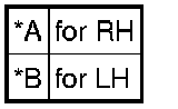
*1: for RH
*2: for LH
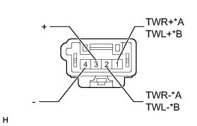
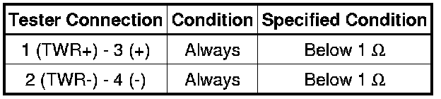
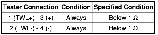
(b) Measure the resistance according to the value(s) in the table below.
Standard Resistance:
for RH
for LH
Text in Illustration
NG -- REPLACE FRONT NO. 3 SPEAKER ASSEMBLY Removal
OK -- REPLACE STEREO COMPONENT AMPLIFIER ASSEMBLY Removal
7. REPLACE FRONT NO. 3 SPEAKER ASSEMBLY
(a) Temporarily replace the front No. 3 speaker assembly with a new or normally functioning one Removal.
OK:
Malfunction disappears.
Result
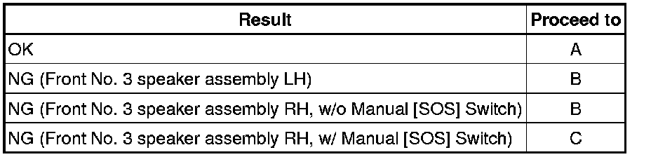
C -- CHECK HARNESS AND CONNECTOR (TELEMATICS TRANSCEIVER - FRONT NO. 3 SPEAKER)
B -- CHECK HARNESS AND CONNECTOR (STEREO COMPONENT AMPLIFIER - FRONT NO. 3 SPEAKER)
OK -- END (FRONT NO. 3 SPEAKER ASSEMBLY IS DEFECTIVE)
8. CHECK HARNESS AND CONNECTOR (STEREO COMPONENT AMPLIFIER - FRONT NO. 3 SPEAKER)
(a) Disconnect the R31 stereo component amplifier assembly connector.
(b) Disconnect the H20*1 and/or H21*2 front No. 3 speaker assembly connector.
*1: for RH
*2: for LH
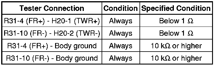
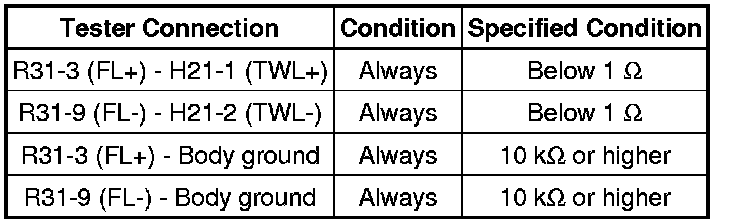
(c) Measure the resistance according to the value(s) in the table below.
Standard Resistance:
for RH
for LH
NG -- REPAIR OR REPLACE HARNESS OR CONNECTOR
OK -- REPLACE STEREO COMPONENT AMPLIFIER ASSEMBLY Removal
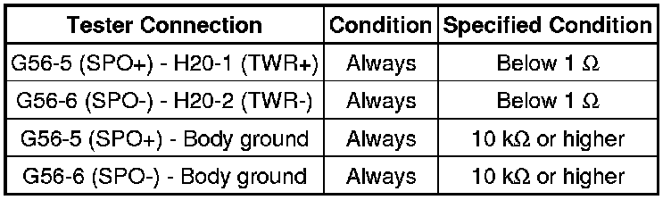
9. CHECK HARNESS AND CONNECTOR (TELEMATICS TRANSCEIVER - FRONT NO. 3 SPEAKER)
(a) Disconnect the G56 telematics transceiver connector.
(b) Disconnect the H20 front No. 3 speaker assembly RH connector.
(c) Measure the resistance according to the value(s) in the table below.
Standard Resistance:
NG -- REPAIR OR REPLACE HARNESS OR CONNECTOR
OK -- Continue to next step.
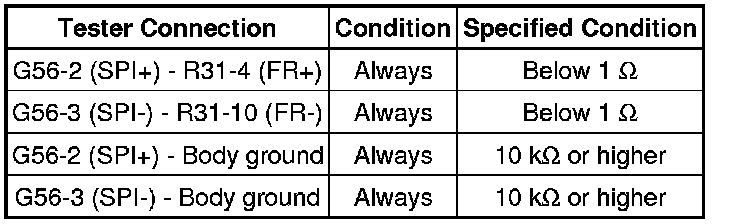
10. CHECK HARNESS AND CONNECTOR (TELEMATICS TRANSCEIVER - STEREO COMPONENT AMPLIFIER)
(a) Disconnect the G56 telematics transceiver connector.
(b) Disconnect the R31 stereo component amplifier assembly connector.
(c) Measure the resistance according to the value(s) in the table below.
Standard Resistance:
NG -- REPAIR OR REPLACE HARNESS OR CONNECTOR
OK -- Continue to next step.
11. INSPECT TELEMATICS TRANSCEIVER
(a) Remove the telematics transceiver Removal.
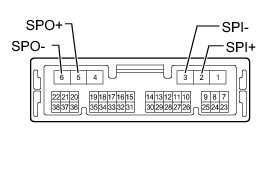
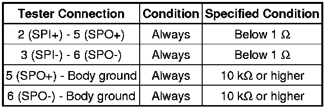
(b) Measure the resistance according to the value(s) in the table below.
Standard Resistance:
NG -- REPLACE TELEMATICS TRANSCEIVER Removal
OK -- REPLACE STEREO COMPONENT AMPLIFIER ASSEMBLY Removal
12. INSPECT FRONT NO. 2 SPEAKER ASSEMBLY
(a) Disconnect the J3*1 and/or K2*2 front No. 2 speaker assembly connector.
*1: for RH
*2: for LH
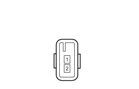
(b) Measure the resistance according to the value(s) in the table below.
Standard Resistance:

NG -- REPLACE FRONT NO. 2 SPEAKER ASSEMBLY Removal
OK -- Continue to next step.
13. CHECK HARNESS AND CONNECTOR (STEREO COMPONENT AMPLIFIER - FRONT NO. 2 SPEAKER)
(a) Disconnect the R33 stereo component amplifier assembly connector.
(b) Disconnect the J3*1 and/or K2*2 front No. 2 speaker assembly connector.
*1: for RH
*2: for LH
Measure the resistance according to the value(s) in the table below.
Standard Resistance:
for RH
for LH
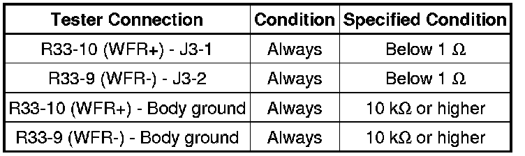
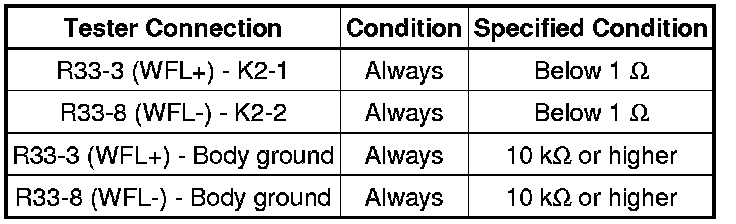
NG -- REPAIR OR REPLACE HARNESS OR CONNECTOR
OK -- REPLACE STEREO COMPONENT AMPLIFIER ASSEMBLY Removal
14. INSPECT FRONT NO. 4 SPEAKER ASSEMBLY
(a) Disconnect the H13 front No. 4 speaker assembly connector.
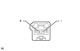
(b) Measure the resistance according to the value(s) in the table below.
Standard Resistance:

NG -- REPLACE FRONT NO. 4 SPEAKER ASSEMBLY Removal
OK -- Continue to next step.
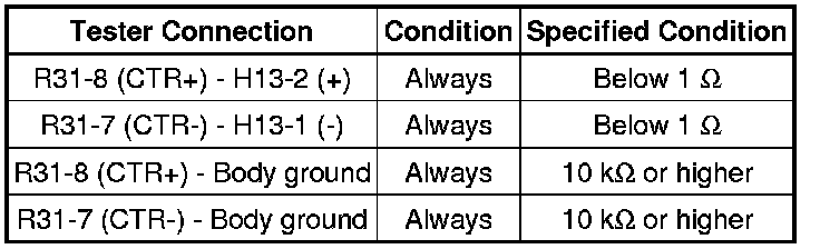
15. CHECK HARNESS AND CONNECTOR (STEREO COMPONENT AMPLIFIER - FRONT NO. 4 SPEAKER)
(a) Disconnect the R31 stereo component amplifier assembly connector.
(b) Disconnect the H13 front No. 4 speaker assembly connector.
(c) Measure the resistance according to the value(s) in the table below.
Standard Resistance:
NG -- REPAIR OR REPLACE HARNESS OR CONNECTOR
OK -- REPLACE STEREO COMPONENT AMPLIFIER ASSEMBLY Removal
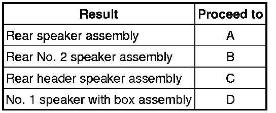
16. CHECK REAR SIDE SPEAKER
(a) Check which speakers are malfunctioning.
Result
D -- INSPECT NO. 1 SPEAKER WITH BOX ASSEMBLY
C -- INSPECT REAR HEADER SPEAKER ASSEMBLY
B -- INSPECT REAR NO. 2 SPEAKER ASSEMBLY
A -- Continue to next step.
17. INSPECT REAR SPEAKER ASSEMBLY
(a) Disconnect the L1*1 and/or M1*2 rear speaker assembly connector.
*1: for RH
*2: for LH
(b) Measure the resistance according to the value(s) in the table below.
Standard Resistance:

NG -- REPLACE REAR SPEAKER ASSEMBLY Removal
OK -- Continue to next step.
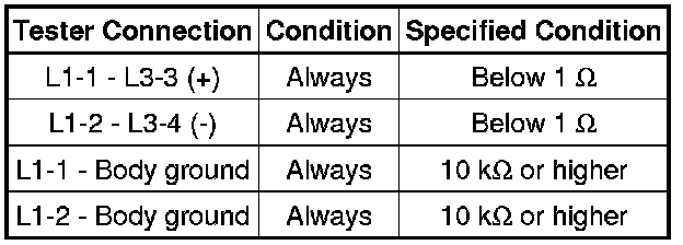
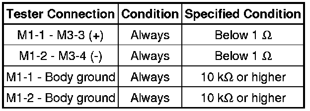
18. CHECK HARNESS AND CONNECTOR (REAR SPEAKER - REAR NO. 2 SPEAKER)
*1: for RH
*2: for LH
(a) Disconnect the L1*1 and/or M1*2 rear speaker assembly connector.
(b) Disconnect the L3*1 and/or M3*2 rear No. 2 speaker assembly connector.
(c) Measure the resistance according to the value(s) in the table below.
Standard Resistance:
for RH
for LH
NG -- REPAIR OR REPLACE HARNESS OR CONNECTOR
OK -- Continue to next step.
19. INSPECT REAR NO. 2 SPEAKER ASSEMBLY
(a) Disconnect the L3*1 and/or M3*2 rear No. 2 speaker assembly connector.
*1: for RH
*2: for LH
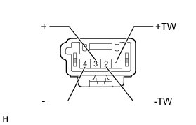
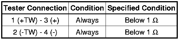
(b) Measure the resistance according to the value(s) in the table below.
Standard Resistance:
NG -- REPLACE REAR NO. 2 SPEAKER ASSEMBLY Removal
OK -- REPLACE STEREO COMPONENT AMPLIFIER ASSEMBLY Removal
20. INSPECT REAR NO. 2 SPEAKER ASSEMBLY
(a) Disconnect the L3*1 and/or M3*2 rear No. 2 speaker assembly connector.
*1: for RH
*2: for LH
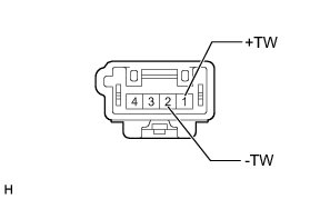
(b) Measure the resistance according to the value(s) in the table below.
Standard Resistance:

NG -- REPLACE REAR NO. 2 SPEAKER ASSEMBLY Removal
OK -- Continue to next step.
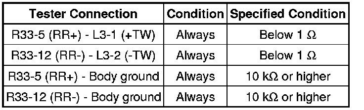
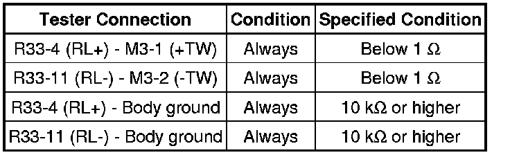
21. CHECK HARNESS AND CONNECTOR (STEREO COMPONENT AMPLIFIER - REAR NO. 2 SPEAKER)
(a) Disconnect the R33 stereo component amplifier assembly connector.
(b) Disconnect the L3*1 and/or M3*2 rear No. 2 speaker assembly connector.
*1: for RH
*2: for LH
(c) Measure the resistance according to the value(s) in the table below.
Standard Resistance:
for RH
for LH
NG -- REPAIR OR REPLACE HARNESS OR CONNECTOR
OK -- REPLACE STEREO COMPONENT AMPLIFIER ASSEMBLY Removal
22. INSPECT REAR HEADER SPEAKER ASSEMBLY
(a) Disconnect the Q15*1 and/or R16*2 rear header speaker assembly connector.
*1: for RH
*2: for LH
(b) Measure the resistance according to the value(s) in the table below.
Standard Resistance:

NG -- REPLACE REAR HEADER SPEAKER ASSEMBLY Removal
OK -- Continue to next step.
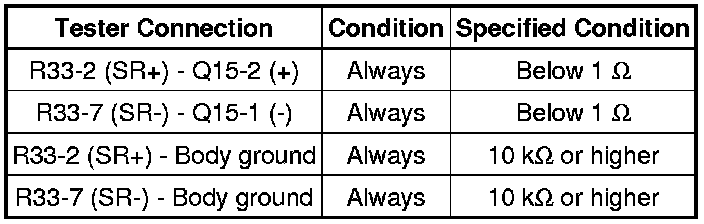
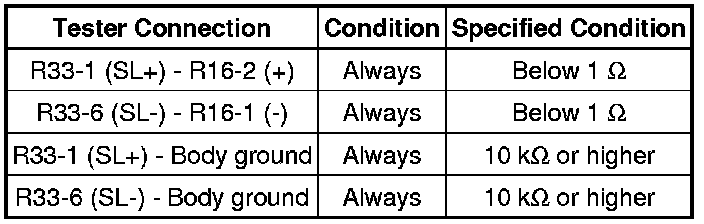
23. CHECK HARNESS AND CONNECTOR (STEREO COMPONENT AMPLIFIER - REAR HEADER SPEAKER)
(a) Disconnect the R33 stereo component amplifier assembly connector.
(b) Disconnect the Q15*1 and/or R16*2 rear header speaker assembly connector.
*1: for RH
*2: for LH
(c) Measure the resistance according to the value(s) in the table below.
Standard Resistance:
for RH
for LH
NG -- REPAIR OR REPLACE HARNESS OR CONNECTOR
OK -- REPLACE STEREO COMPONENT AMPLIFIER ASSEMBLY Removal
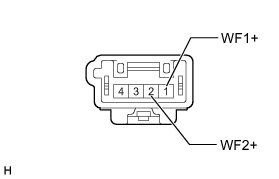
24. INSPECT NO. 1 SPEAKER WITH BOX ASSEMBLY
(a) Disconnect the R24 No. 1 speaker with box assembly connector.
(b) Measure the resistance according to the value(s) in the table below.
Standard Resistance:

NG -- REPLACE NO. 1 SPEAKER WITH BOX ASSEMBLY Removal
OK -- Continue to next step.
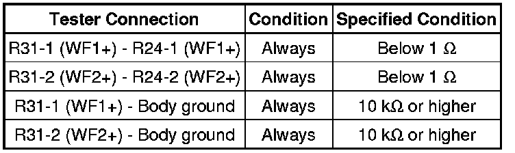
25. CHECK HARNESS AND CONNECTOR (STEREO COMPONENT AMPLIFIER - NO. 1 SPEAKER WITH BOX)
(a) Disconnect the R31 stereo component amplifier assembly connector.
(b) Disconnect the R24 No. 1 speaker with box assembly connector.
Standard Resistance:
NG -- REPAIR OR REPLACE HARNESS OR CONNECTOR
OK -- REPLACE STEREO COMPONENT AMPLIFIER ASSEMBLY Removal