"CHK" message(s) are displayed on the SIGNAL CHECK screen.
PARK ASSIST / MONITORING: REAR VIEW MONITOR SYSTEM (w/ Side Monitor System): "CHK" message(s) are displayed on the SIGNAL CHECK screen.
- "CHK" message(s) are displayed on the SIGNAL CHECK screen.
DESCRIPTION
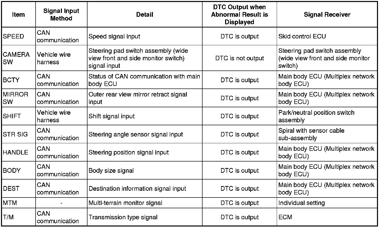
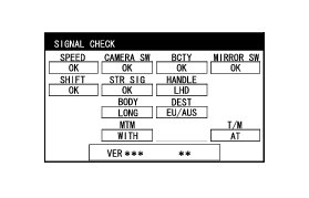
On the SIGNAL CHECK screen, it is possible to check if the signals sent to the parking assist ECU are normal Diagnosis System.
HINT
* On the SIGNAL CHECK screen, "OK" (blue) is displayed for items with a normal inspection result or input state.
* On the SIGNAL CHECK screen, "CHK" (red) is displayed for items with an abnormal inspection result or input state.
* Displayed items may differ depending on vehicle specifications.
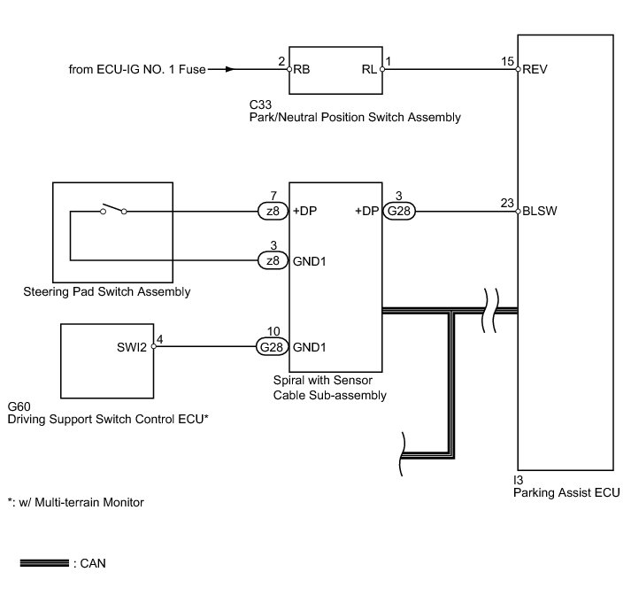
WIRING DIAGRAM
INSPECTION PROCEDURE
NOTICE:
* When "System initializing" is displayed on the display and navigation module display after the battery cable is disconnected, correct the steering angle neutral point Side Monitor System.
* Depending on the parts that are replaced or operations that are performed during vehicle inspection or maintenance, calibration of other systems as well as the parking assist monitor system may be needed Repair Instruction - Initialization.
PROCEDURE
1. CHECK DISPLAY CHECK MODE
(a) Check which items display "CHK" (red) on the SIGNAL CHECK screen.
Result

D -- CHECK FOR DTC Rear View Monitor System (w/ Side Monitor System)
C -- CHECK REAR VIEW MONITOR SYSTEM
B -- CHECK PARKING ASSIST ECU
A -- Continue to next step.
2. INSPECT STEERING PAD SWITCH ASSEMBLY (WIDE VIEW FRONT AND SIDE MONITOR SWITCH)
(a) Remove the steering pad switch assembly Component Tests and General Diagnostics.
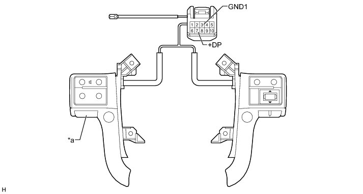
Text in Illustration

(b) Measure the resistance according to the value(s) in the table below.
Standard Resistance:

NG -- REPLACE STEERING PAD SWITCH ASSEMBLY Component Tests and General Diagnostics
OK -- Continue to next step.
3. INSPECT SPIRAL WITH SENSOR CABLE SUB-ASSEMBLY
(a) Remove the spiral with sensor cable sub-assembly Removal.
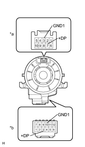
(b) Measure the resistance according to the value(s) in the table below.
Standard Resistance:
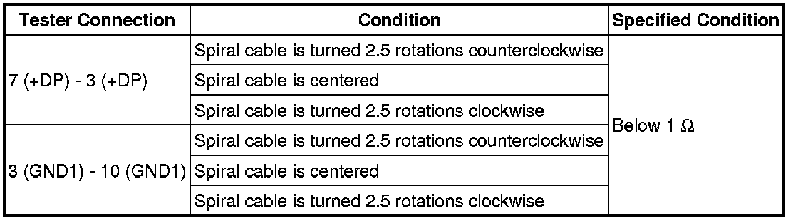
CAUTION:
The spiral cable is an important part of the SRS airbag system. Incorrect removal or installation of the spiral cable may prevent the airbag from deploying. Be sure to read the Precaution in the SRS section Service Precautions.
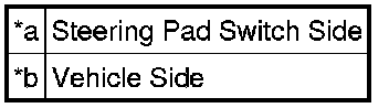
Text in Illustration
NG -- REPLACE SPIRAL WITH SENSOR CABLE SUB-ASSEMBLY Removal
OK -- Continue to next step.
4. CHECK HARNESS AND CONNECTOR (SPIRAL WITH SENSOR CABLE - BODY GROUND)
(a) Disconnect the G28 spiral with sensor cable sub-assembly connector.
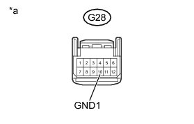
(b) Measure the resistance according to the value(s) in the table below.
Standard Resistance:

Text in Illustration

NG -- CHECK HARNESS AND CONNECTOR (SPIRAL WITH SENSOR CABLE - DRIVING SUPPORT SWITCH CONTROL ECU)
OK -- Continue to next step.
5. CHECK HARNESS AND CONNECTOR (SPIRAL WITH SENSOR CABLE - PARKING ASSIST ECU)
(a) Disconnect the G28 spiral with sensor cable sub-assembly connector.
(b) Disconnect the I3 parking assist ECU connector.
(c) Measure the resistance according to the value(s) in the table below.
Standard Resistance:

NG -- REPAIR OR REPLACE HARNESS OR CONNECTOR Removal
OK -- REPLACE SPIRAL WITH SENSOR CABLE SUB-ASSEMBLY Removal
6. CHECK HARNESS AND CONNECTOR (SPIRAL WITH SENSOR CABLE - DRIVING SUPPORT SWITCH CONTROL ECU)
(a) Disconnect the G28 spiral with sensor cable sub-assembly connector.
(b) Disconnect the G60 driving support switch control ECU connector.
(c) Measure the resistance according to the value(s) in the table below.
Standard Resistance:

NG -- REPAIR OR REPLACE HARNESS OR CONNECTOR
OK -- Continue to next step.
7. REPLACE DRIVING SUPPORT SWITCH CONTROL ECU
(a) Replace the driving support switch control ECU with a new or normally functioning one Removal.
(b) Check that "CAMERA SW" displays "OK" on the SIGNAL CHECK screen.
NG -- REPLACE PARKING ASSIST ECU Removal
OK -- END (DRIVING SUPPORT SWITCH CONTROL ECU IS DEFECTIVE)
8. CHECK PARKING ASSIST ECU
(a) Disconnect the I3 parking assist ECU connector.
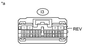
(b) Measure the voltage according to the value(s) in the table below.
Standard Voltage:

Text in Illustration

NG -- CHECK HARNESS AND CONNECTOR (PARKING ASSIST ECU - PARK/NEUTRAL POSITION SWITCH)
OK -- REPAIR OR REPLACE HARNESS OR CONNECTOR
9. CHECK HARNESS AND CONNECTOR (PARKING ASSIST ECU - PARK/NEUTRAL POSITION SWITCH)
(a) Disconnect the I3 parking assist ECU connector.
(b) Disconnect the C33 park/neutral position switch assembly connector.
(c) Measure the resistance according to the value(s) in the table below.
Standard Resistance:

NG -- REPAIR OR REPLACE HARNESS OR CONNECTOR
OK -- REPLACE PARK/NEUTRAL POSITION SWITCH ASSEMBLY Removal
10. CHECK REAR VIEW MONITOR SYSTEM
(a) Check if the side monitor system or wide view front monitor system has the problem.
Result
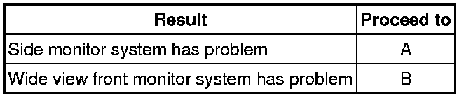
B -- GO TO WIDE VIEW FRONT MONITOR SYSTEM Problem Symptoms Table
A -- GO TO SIDE MONITOR SYSTEM Problem Symptoms Table