Part 3
1UR-FE ENGINE CONTROL: SFI SYSTEM: P1604: Startability Malfunction
P1604 - Startability Malfunction
61. CHECK HARNESS AND CONNECTOR (ENGINE COOLANT TEMPERATURE SENSOR - ECM)
(a) Disconnect the engine coolant temperature sensor connector.
(b) Disconnect the ECM connector.
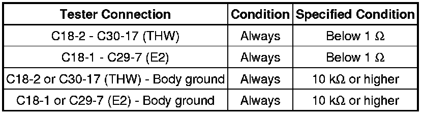
(c) Measure the resistance according to the value(s) in the table below.
Standard Resistance:
HINT
- Jiggle the wire harness and connector to increase the likelihood of detecting malfunctions that do not always occur.
- Make sure there is not an excessive amount of force applied to the wire harness.
- If the wire harness or connector is malfunctioning, after replacing or repairing it, check if engine starting trouble occurs again. If engine starting trouble occurs, replace the ECM. If engine starting trouble still occurs, proceed to step 74 and perform fuel system troubleshooting A (steps 97 to 104), fuel system troubleshooting B (steps 105 to 107), intake system troubleshooting (steps 108 to 110), and ignition system troubleshooting (steps 111 to 116), in that order.
NG -- REPAIR OR REPLACE HARNESS OR CONNECTOR
OK -- Continue to next step.
62. CHECK MASS AIR FLOW METER ASSEMBLY
(a) Connect the Techstream to the DLC3.
(b) Start the engine and warm it up until the engine coolant temperature reaches 75°C (167°F) or higher.
HINT
The A/C switch and all accessory switches should be off, and the shift lever should be in N or P.
(c) Turn the Techstream on.
(d) Enter the following menus: Powertrain / Engine and ECT / Data List / MAF.
(e) Check MAF in the Data List during idling.
Standard:
3.4 to 6.2 gm/s.
HINT
If the mass air flow meter is malfunctioning, after replacing it, check if engine starting trouble occurs again. If engine starting trouble occurs, replace the ECM. If engine starting trouble still occurs, proceed to step 74 and perform fuel system troubleshooting A (steps 97 to 104), fuel system troubleshooting B (steps 105 to 107), intake system troubleshooting (steps 108 to 110), and ignition system troubleshooting (steps 111 to 116), in that order.
NG -- REPLACE MASS AIR FLOW METER ASSEMBLY Removal
OK -- Continue to next step.
63. CHECK HARNESS AND CONNECTOR (MASS AIR FLOW METER - ECM)
(a) Disconnect the mass air flow meter connector.
(b) Disconnect the ECM connector.
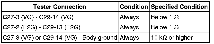
(c) Measure the resistance according to the value(s) in the table below.
Standard Resistance:
HINT
- Jiggle the wire harness and connector to increase the likelihood of detecting malfunctions that do not always occur.
- Make sure there is not an excessive amount of force applied to the wire harness.
- If the wire harness or connector is malfunctioning, after replacing or repairing it, check if engine starting trouble occurs again. If engine starting trouble occurs, replace the ECM. If engine starting trouble still occurs, proceed to step 74 and perform fuel system troubleshooting A (steps 97 to 104), fuel system troubleshooting B (steps 105 to 107), intake system troubleshooting (steps 108 to 110), and ignition system troubleshooting (steps 111 to 116), in that order.
NG -- REPAIR OR REPLACE HARNESS OR CONNECTOR
OK -- Continue to next step.
64. READ VALUE USING TECHSTREAM
(a) Connect the Techstream to the DLC3.
(b) Turn the engine switch on (IG).
(c) Enter the following menus: Powertrain / Engine and ECT / Data List / Long FT and Atmosphere Pressure.
Result

B -- CHECK FUEL PRESSURE
A -- Continue to next step.
65. PERFORM SIMULATION TEST
(a) Remove the EFI and ETCS fuses from the engine room relay block.
(b) After 60 seconds or more elapse, install the EFI and ETCS fuses.
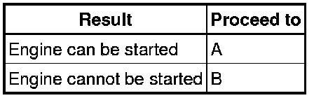
(c) Check if the engine can be started.
Result
B -- CHECK FUEL PRESSURE
A -- Continue to next step.
66. INSPECT AIR FUEL RATIO SENSOR
(a) Connect the Techstream to the DLC3.
(b) Start the engine.
(c) Turn the Techstream on.
(d) Enter the following menus: Powertrain / Engine and ECT / Data List / Fuel System Status #1 and Fuel System Status #2.
(e) Confirm that Fuel System Status #1 and Fuel System Status #2 are both CL.
(f) Enter the following menus: Powertrain / Engine and ECT / Data List / AF Lambda B1S1 and AF Lambda B2S1.
(g) Confirm that AF Lambda B1S1 and AF Lambda B2S1 are both within the range of 0.95 to 1.05 when idling.
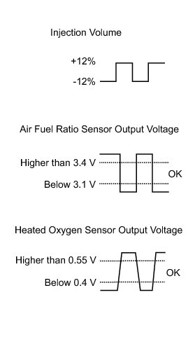
(h) Enter the following menus: Powertrain / Engine and ECT / Active Test / Control the Injection Volume for A/F sensor.
(i) Read the output voltage from the air fuel ratio sensor when increasing and decreasing the fuel injection volume.
Standard:

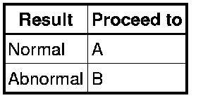
Result
HINT
- The air fuel ratio sensor has an output delay of a few seconds and the heated oxygen sensor has a maximum output delay of approximately 20 seconds.
- If the air fuel ratio sensor is malfunctioning, after replacing it, check if engine starting trouble occurs again. If engine starting trouble occurs, replace the ECM. If engine starting trouble still occurs, proceed to step 74 and perform fuel system troubleshooting A (steps 97 to 104), fuel system troubleshooting B (steps 105 to 107), intake system troubleshooting (steps 108 to 110), and ignition system troubleshooting (steps 111 to 116), in that order.
B -- REPLACE AIR FUEL RATIO SENSOR Removal
A -- Continue to next step.
67. PERFORM SIMULATION TEST
(a) Check if the idling speed is stable after starting the engine.
OK:
Speed is stable.
HINT
After replacing the fuel injector or mass air flow meter, check if engine starting trouble occurs again. If engine starting trouble occurs, replace the ECM. If engine starting trouble still occurs, proceed to step 74 and perform fuel system troubleshooting A (steps 97 to 104), fuel system troubleshooting B (steps 105 to 107), intake system troubleshooting (steps 108 to 110), and ignition system troubleshooting (steps 111 to 116), in that order.
NG -- REPLACE FUEL INJECTOR ASSEMBLY Removal
OK -- REPLACE MASS AIR FLOW METER ASSEMBLY Removal
68. CHECK FUEL PRESSURE
(a) Inspect the fuel pressure Fuel System.
NG -- PERFORM ACTIVE TEST USING TECHSTREAM (CONTROL THE FUEL PUMP / SPEED)
OK -- Continue to next step.
69. CHECK SPARK PLUG
(a) Inspect the spark plugs Testing and Inspection.
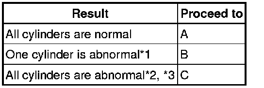
Result
HINT
- *1: If one cylinder is abnormal, replace the spark plug of that cylinder and inspect the ignition and fuel system for that cylinder. After performing repairs, check if engine starting trouble occurs again. If engine starting trouble still occurs, proceed to step 74 and perform fuel system troubleshooting A (steps 97 to 104), fuel system troubleshooting B (steps 105 to 107), intake system troubleshooting (steps 108 to 110), and ignition system troubleshooting (steps 111 to 116), in that order.
- *2: If all cylinders are abnormal, replace the spark plugs of all cylinders and check if engine starting trouble occurs again. If engine starting trouble still occurs, proceed to step 74 and perform fuel system troubleshooting A (steps 97 to 104), fuel system troubleshooting B (steps 105 to 107), intake system troubleshooting (steps 108 to 110), and ignition system troubleshooting (steps 111 to 116), in that order.
- *3: Engine starting trouble may occur if the vehicle is driven extremely short distances repeatedly.
C -- REPLACE SPARK PLUG (ALL) Removal
B -- REPLACE SPARK PLUG (ABNORMAL CYLINDER) Removal
A -- Continue to next step.
70. CONFIRM VEHICLE CONDITION
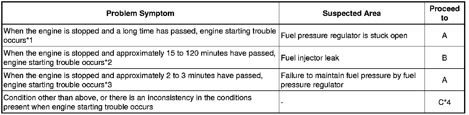
(a) Confirm the conditions present when the malfunction occurred based on the customer problem analysis.
Result
HINT
*1: The fuel pressure regulator may be stuck open. Attach a fuel pressure gauge and check the ability of the system to maintain fuel pressure after stopping the engine.
*2: Fuel may be leaking from a fuel injector.
*3: The fuel pressure regulator may not be able to maintain the fuel pressure. Attach a fuel pressure gauge and check the ability of the fuel pressure regulator to maintain fuel pressure after stopping the engine.
*4: From step 74, perform fuel system troubleshooting A (steps 97 to 104), fuel system troubleshooting B (steps 105 to 107), intake system troubleshooting (steps 108 to 110), and ignition system troubleshooting (steps 111 to 116), in that order.
C -- CHECK MALFUNCTION CONDITION
B -- CHECK FUEL INJECTOR ASSEMBLY
A -- Continue to next step.
71. CHECK FUEL PRESSURE
HINT
For the fuel pressure inspection, refer to the following procedures Fuel System.
(a) Attach a fuel pressure gauge and check the fuel pressure after stopping the engine.
Result

HINT
- If the engine cannot be started, check the fuel pressure after cranking the engine.
- *1: From step 74, perform fuel system troubleshooting A (steps 97 to 104), fuel system troubleshooting B (steps 105 to 107), intake system troubleshooting (steps 108 to 110), and ignition system troubleshooting (steps 111 to 116), in that order.
B -- REPLACE FUEL PRESSURE REGULATOR ASSEMBLY Removal
A -- CHECK MALFUNCTION CONDITION
72. CHECK FUEL INJECTOR ASSEMBLY
(a) Clean the inside of the surge tank with compressed air.
(b) After stopping the engine, measure the HC concentration inside the surge tank for 15 minutes.
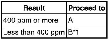
Result
HINT
- If the concentration is 400 ppm or more, a fuel injector may have a sealing problem.
- *1: From step 74, perform fuel system troubleshooting A (steps 97 to 104), fuel system troubleshooting B (steps 105 to 107), intake system troubleshooting (steps 108 to 110), and ignition system troubleshooting (steps 111 to 116), in that order.
B -- CHECK MALFUNCTION CONDITION
A -- REPLACE FUEL INJECTOR ASSEMBLY Removal
73. PERFORM ACTIVE TEST USING TECHSTREAM (CONTROL THE FUEL PUMP / SPEED)
(a) Connect the Techstream to the DLC3.
(b) Turn the engine switch on (IG).
(c) Enter the following menus: Powertrain / Engine and ECT / Active Test / Control the Fuel Pump / Speed.
(d) When performing the Active Test, check for fuel leakage from the fuel pipes.
Result

HINT
- Jiggle the wire harness and connector to increase the likelihood of detecting malfunctions that do not always occur.
- Check if the vehicle ran out of fuel, as engine starting trouble due to running out of fuel is also detected.
- If there are no fuel leaks, after inspecting the fuel pump control system, check if engine starting trouble occurs again. If engine starting trouble still occurs, proceed to step 74 and perform fuel system troubleshooting A (steps 97 to 104), fuel system troubleshooting B (steps 105 to 107), intake system troubleshooting (steps 108 to 110), and ignition system troubleshooting (steps 111 to 116), in that order.
B -- CHECK FUEL PUMP CONTROL SYSTEM Fuel Pump Control Circuit
A -- REPAIR OR REPLACE FUEL LINE
74. CHECK MALFUNCTION CONDITION
(a) If the malfunction could not be identified during the inspections in steps 38, 39, 40 and 47, perform fuel system troubleshooting C (steps 75 to 79).
Result

(b) If the malfunction could not be identified during the inspection in step 45, perform ignition system troubleshooting (steps 80 to 85).
Result

(c) If the malfunction could not be identified during the inspections in steps 55, 56, 57, 58 and 59, perform intake air system troubleshooting (steps 86 to 88). If engine starting trouble still occurs, perform fuel system troubleshooting A (steps 89 to 96).
Result

(d) If the malfunction could not be identified during the inspections in steps 60, 61, 62, 63, 66, 67, 69, 70, 71, 72 and 73, perform fuel system troubleshooting A (steps 97 to 104), fuel system troubleshooting B (steps 105 to 107), intake air system troubleshooting (steps 108 to 110), and ignition system troubleshooting (steps 111 to 116), in that order.
Result

D -- CHECK FUEL PRESSURE
C -- READ VALUE USING TECHSTREAM (ISC LEARNING VALUE)
B -- CHECK CRANKSHAFT POSITION SENSOR
A -- Continue to next step.
75. INSPECT FUEL INJECTOR ASSEMBLY
(a) Inspect the fuel injector assembles Testing and Inspection.
NG -- REPLACE FUEL INJECTOR ASSEMBLY Removal
OK -- Continue to next step.
76. CHECK TERMINAL VOLTAGE (FUEL INJECTOR POWER SOURCE)
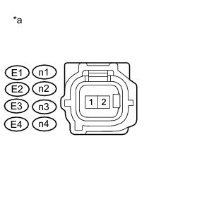
(a) Disconnect the fuel injector connector.
(b) Turn the engine switch on (IG).
(c) Measure the voltage according to the value(s) in the table below.
Standard Voltage:
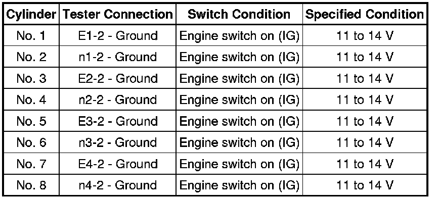
Text in Illustration

HINT
- Jiggle the wire harness and connector to increase the likelihood of detecting malfunctions that do not always occur.
- Make sure there is not an excessive amount of force applied to the wire harness.
NG -- REPAIR POWER SOURCE CIRCUIT Fuel Injector Circuit
OK -- Continue to next step.
77. CHECK HARNESS AND CONNECTOR (FUEL INJECTOR - ECM)
(a) Disconnect the fuel injector connector.
(b) Disconnect the ECM connector.
(c) Measure the resistance according to the value(s) in the table below.
Standard Resistance:
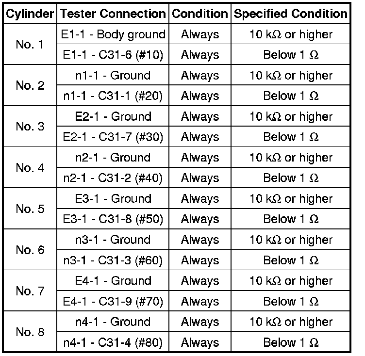
HINT
- Jiggle the wire harness and connector to increase the likelihood of detecting malfunctions that do not always occur.
- Make sure there is not an excessive amount of force applied to the wire harness.
NG -- REPAIR OR REPLACE HARNESS OR CONNECTOR
OK -- Continue to next step.
78. CHECK CRANKSHAFT POSITION SENSOR
(a) Replace the crankshaft position sensor Removal.
(b) Check the engine start operation.
OK:
Malfunction has been repaired successfully.
NG -- CHECK CAMSHAFT POSITION SENSOR
OK -- END (CRANKSHAFT POSITION SENSOR IS DEFECTIVE)
79. CHECK CAMSHAFT POSITION SENSOR
(a) Replace the camshaft position sensor Removal.
(b) Check the engine start operation.
OK:
Malfunction has been repaired successfully.
NG -- REPLACE ECM Removal
OK -- END (CAMSHAFT POSITION SENSOR IS DEFECTIVE)
80. CHECK CRANKSHAFT POSITION SENSOR
(a) Check the tightening and installation condition of the crankshaft position sensor bolt.
(b) Check the connection of the crankshaft position sensor connector.
OK:
Sensor is installed correctly.
NG -- SECURELY REINSTALL SENSOR Installation
OK -- Continue to next step.
81. CHECK CAMSHAFT POSITION SENSOR
(a) Check the tightening and installation condition of the camshaft position sensor bolt.
(b) Check the connection of the camshaft position sensor connector.
OK:
Sensor is installed correctly.
NG -- SECURELY REINSTALL SENSOR Installation
OK -- Continue to next step.
82. CHECK HARNESS AND CONNECTOR (CRANKSHAFT POSITION SENSOR - ECM)
(a) Disconnect the crankshaft position sensor connector.
(b) Disconnect the ECM connector.
(c) Measure the resistance according to the value(s) in the table below.
Standard Resistance:
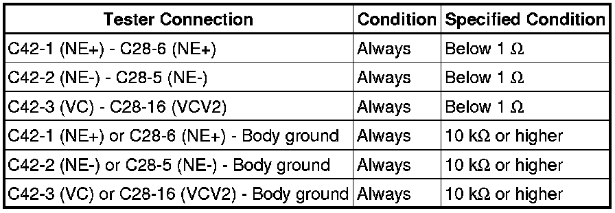
HINT
- Jiggle the wire harness and connector to increase the likelihood of detecting malfunctions that do not always occur.
- Make sure there is not an excessive amount of force applied to the wire harness.
NG -- REPAIR OR REPLACE HARNESS OR CONNECTOR
OK -- Continue to next step.
83. CHECK HARNESS AND CONNECTOR (CAMSHAFT POSITION SENSOR - ECM)
(a) Disconnect the camshaft position sensor connector.
(b) Disconnect the ECM connector.
(c) Measure the resistance according to the value(s) in the table below.
Standard Resistance:
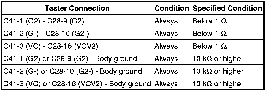
HINT
- Jiggle the wire harness and connector to increase the likelihood of detecting malfunctions that do not always occur.
- Make sure there is not an excessive amount of force applied to the wire harness.
NG -- REPAIR OR REPLACE HARNESS OR CONNECTOR
OK -- Continue to next step.
84. CHECK CRANKSHAFT POSITION SENSOR
(a) Replace the crankshaft position sensor Removal.
(b) Check the engine start operation.
OK:
Malfunction has been repaired successfully.
NG -- CHECK CAMSHAFT POSITION SENSOR
OK -- END (CRANKSHAFT POSITION SENSOR IS DEFECTIVE)
85. CHECK CAMSHAFT POSITION SENSOR
(a) Replace the camshaft position sensor Removal.
(b) Check the engine start operation.
OK:
Malfunction has been repaired successfully.
NG -- REPLACE ECM Removal
OK -- END (CAMSHAFT POSITION SENSOR IS DEFECTIVE)
86. READ VALUE USING TECHSTREAM (ISC LEARNING VALUE)
(a) Connect the Techstream to the DLC3.
(b) Turn the engine switch on (IG).
(c) Start the engine and warm it up until the engine coolant temperature stabilizes with the A/C switch and all the accessory switches off.
(d) Enter the following menus: Powertrain / Engine and ECT / Data List / ISC Learning Value.
Result

B -- INSPECT ENGINE COOLANT TEMPERATURE SENSOR
A -- Continue to next step.
87. CHECK CYLINDER COMPRESSION PRESSURE
(a) Inspect the compression Engine.
NG -- REPAIR OR REPLACE ENGINE ASSEMBLY
OK -- CHECK VALVE TIMING
88. INSPECT ENGINE COOLANT TEMPERATURE SENSOR
(a) Inspect the engine coolant temperature sensor Testing and Inspection.
NG -- REPLACE ENGINE COOLANT TEMPERATURE SENSOR Removal
OK -- Continue to next step.
89. CHECK FUEL PRESSURE
HINT
For the fuel pressure inspection, refer to the following procedures Fuel System.
(a) Attach a fuel pressure gauge and check the fuel pressure when cranking the engine and after stopping the engine.
Result

NG -- PERFORM ACTIVE TEST USING TECHSTREAM (CONTROL THE FUEL PUMP / SPEED)
OK -- Continue to next step.
90. READ VALUE USING TECHSTREAM (LONG FT)
(a) Connect the Techstream to the DLC3.
(b) Turn the engine switch on (IG).
(c) Enter the following menus: Powertrain / Engine and ECT / Data List / Long FT.
Result

B -- REPLACE FUEL INJECTOR ASSEMBLY Removal
A -- Continue to next step.