Power Back Door Warning Buzzer Circuit
DOOR / HATCH: POWER BACK DOOR SYSTEM: Power Back Door Warning Buzzer Circuit
Power Back Door Warning Buzzer Circuit
DESCRIPTION
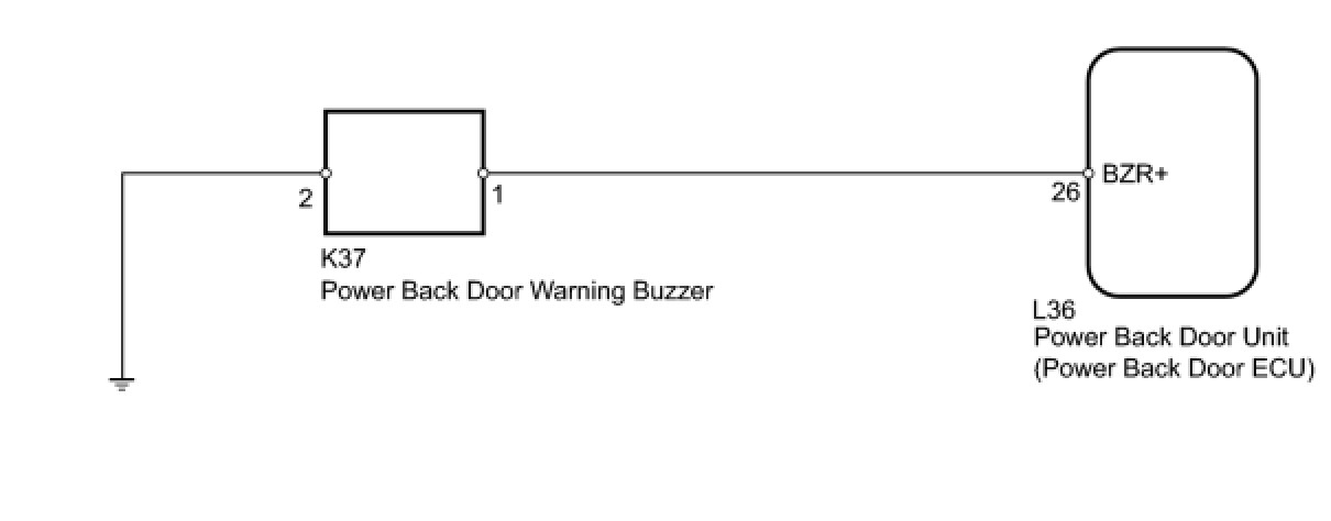
The power back door unit (power back door ECU) receives the power back door ON/OFF switch signal to sound the power back door warning buzzer.
WIRING DIAGRAM
INSPECTION PROCEDURE
PROCEDURE
1. PERFORM ACTIVE TEST USING TECHSTREAM (POWER BACK DOOR WARNING BUZZER)
(a) Select the Active Test, use the Techstream to generate a control command, and check that the power back door warning buzzer sounds.
Back Door

OK:
Power back door warning buzzer sounds normally.
NG -- CHECK HARNESS AND CONNECTOR (BUZZER - UNIT AND BODY GROUND)
OK -- REPLACE POWER BACK DOOR UNIT ASSEMBLY
2. CHECK HARNESS AND CONNECTOR (BUZZER - UNIT AND BODY GROUND)
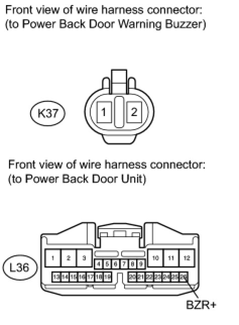
(a) Disconnect the K37 buzzer connector.
(b) Disconnect the L36 ECU connector.
(c) Measure the resistance according to the value(s) in the table below.
Standard Resistance:

NG -- REPAIR OR REPLACE HARNESS OR CONNECTOR
OK -- Continue to next step.
3. REPLACE POWER BACK DOOR WARNING BUZZER
(a) Replace the power back door warning buzzer Removal.
NEXT -- Continue to next step.
4. PERFORM ACTIVE TEST USING TECHSTREAM (POWER BACK DOOR WARNING BUZZER)
(a) Select the Active Test, use the Techstream to generate a control command, and check that the power back door warning buzzer sounds.
Back Door

OK:
Power back door warning buzzer sounds normally.
NG -- REPLACE POWER BACK DOOR UNIT ASSEMBLY
OK -- END (POWER BACK DOOR WARNING BUZZER IS DEFECTIVE)