Power Back Door Opener/Closer Switch Circuit
DOOR / HATCH: POWER BACK DOOR SYSTEM: Power Back Door Opener / Closer Switch Circuit
Power Back Door Opener / Closer Switch Circuit
DESCRIPTION
The combination switch (power back door opener/closer switch) only turns on while the switch is being pressed, and turns off when the switch is released.
When the switch is on, a power back door operation request signal is input to the main body ECU to operate the back door.
WIRING DIAGRAM
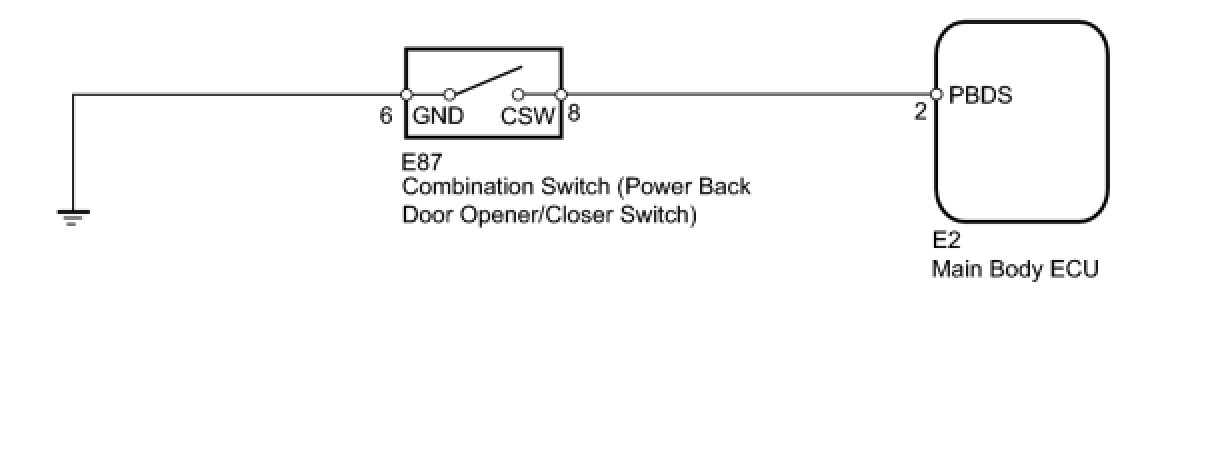
INSPECTION PROCEDURE
PROCEDURE
1. READ VALUE USING TECHSTREAM (POWER BACK DOOR OPENER/CLOSER SWITCH)
(a) Check the Data List for proper functioning of the power back door opener/closer switch.
Main Body

OK:
The display is as specified in the normal condition.
NG -- INSPECT COMBINATION SWITCH ASSEMBLY (POWER BACK DOOR OPENER/CLOSER SWITCH)
OK -- REPLACE MAIN BODY ECU
2. INSPECT COMBINATION SWITCH ASSEMBLY (POWER BACK DOOR OPENER/CLOSER SWITCH)
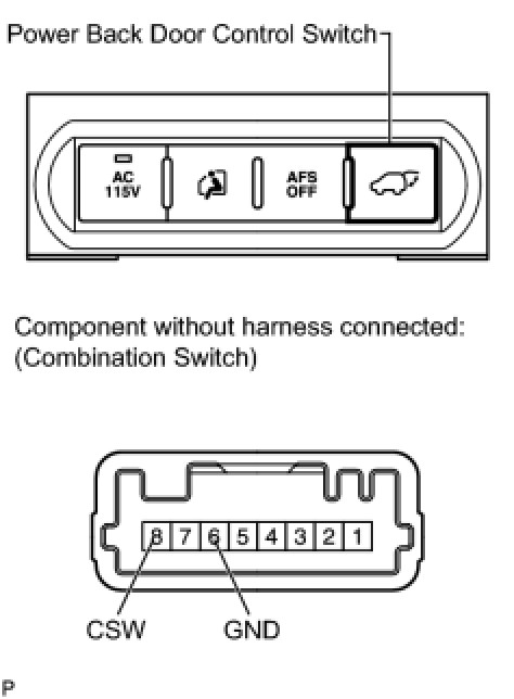
(a) Remove the combination switch Removal.
(b) Measure the resistance according to the value(s) in the table below.
Standard Resistance:

NG -- REPLACE COMBINATION SWITCH ASSEMBLY
OK -- Continue to next step.
3. CHECK HARNESS AND CONNECTOR (SWITCH - ECU AND BODY GROUND)
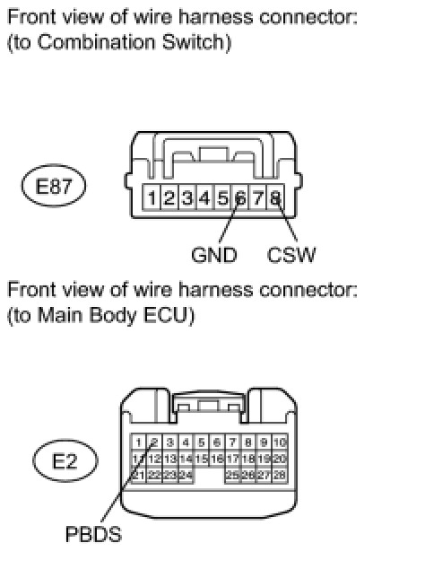
(a) Disconnect the E87 switch connector.
(b) Disconnect the E2 ECU connector.
(c) Measure the resistance according to the value(s) in the table below.
Standard Resistance:

NG -- REPAIR OR REPLACE HARNESS OR CONNECTOR
OK -- REPLACE MAIN BODY ECU