Part 1
AUDIO / VIDEO: AUDIO AND VISUAL SYSTEM: Speaker Circuit
Speaker Circuit
DESCRIPTION
The stereo component amplifier sends sound signals to the speakers.
WIRING DIAGRAM
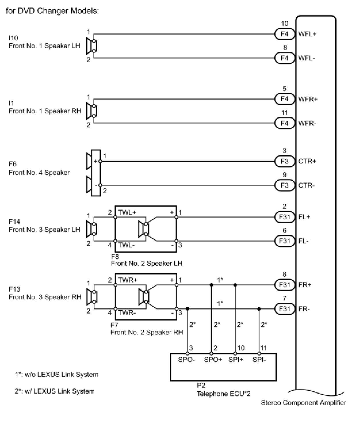
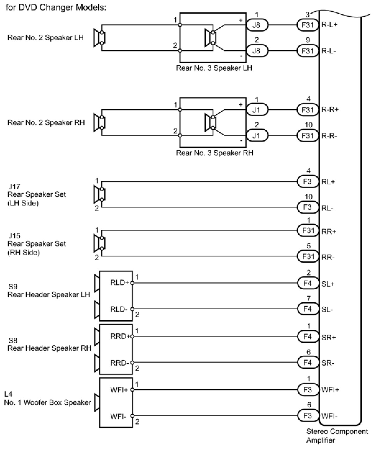
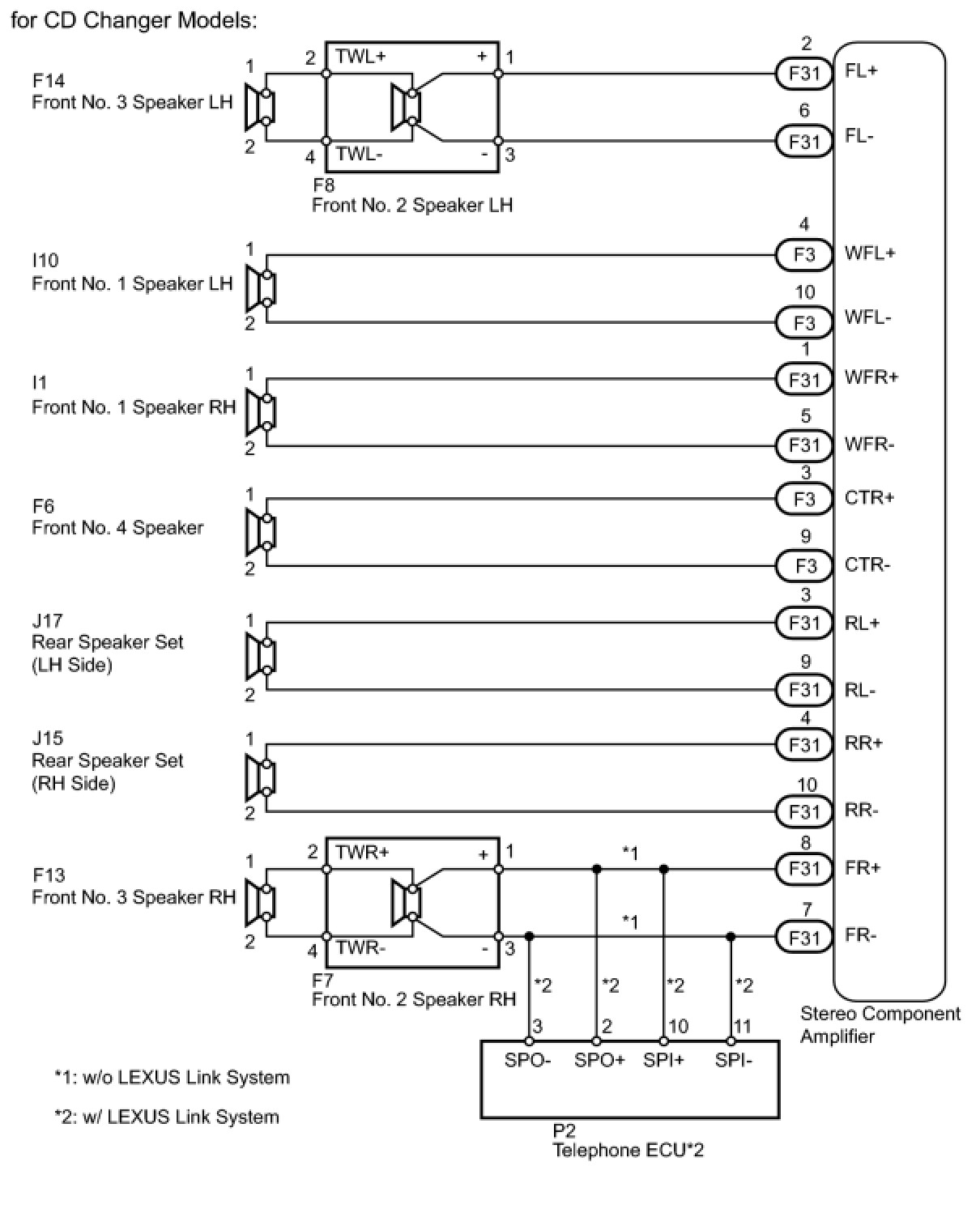
INSPECTION PROCEDURE
PROCEDURE
1. CHECK AUDIO MODELS
(a) Check the audio model.
Result

B -- CHECK SPEAKER
A -- Continue to next step.
2. CHECK SPEAKER
(a) Check the malfunctioning speakers.
Result

B -- CHECK SPEAKER
A -- Continue to next step.
3. CHECK SPEAKER
(a) Check the malfunctioning speakers.
Result

D -- CHECK FRONT NO. 3 SPEAKER ASSEMBLY
C -- INSPECT FRONT NO. 1 SPEAKER ASSEMBLY
B -- INSPECT FRONT NO. 2 SPEAKER ASSEMBLY
A -- Continue to next step.
4. INSPECT FRONT NO. 4 SPEAKER ASSEMBLY
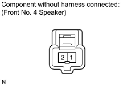
(a) Disconnect the F6 speaker connector.
(b) Measure the resistance according to the value(s) in the table below.
Standard Resistance:

NG -- REPLACE FRONT NO. 4 SPEAKER ASSEMBLY
OK -- Continue to next step.
5. CHECK HARNESS AND CONNECTOR (STEREO COMPONENT AMPLIFIER - FRONT NO. 4 SPEAKER)
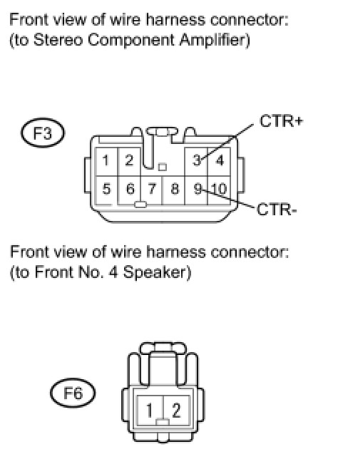
(a) Disconnect the F6 speaker connector.
(b) Disconnect the F3 amplifier connector.
(c) Measure the resistance according to the value(s) in the table below.
Standard Resistance:

NG -- REPAIR OR REPLACE HARNESS OR CONNECTOR
OK -- REPLACE STEREO COMPONENT AMPLIFIER ASSEMBLY
6. INSPECT FRONT NO. 2 SPEAKER ASSEMBLY
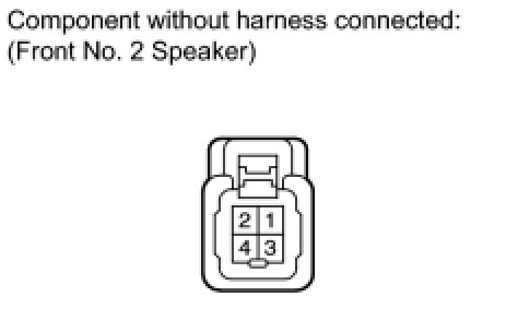
(a) Disconnect the F8 and F7 speaker connectors.
(b) Measure the resistance according to the value(s) in the table below.
Standard Resistance:

NG -- REPLACE FRONT NO. 2 SPEAKER ASSEMBLY
OK -- Continue to next step.
7. CHECK DEFECTIVE SPEAKER AND VEHICLE EQUIPMENT
(a) Check which side of the vehicle the defective speaker is on. Also, check if the vehicle is equipped with the LEXUS Link System.
Result

B -- CHECK HARNESS AND CONNECTOR (STEREO COMPONENT AMPLIFIER - FRONT NO. 2 SPEAKER)
A -- Continue to next step.
8. CHECK HARNESS AND CONNECTOR (TELEPHONE ECU - STEREO COMPONENT AMPLIFIER AND FRONT NO. 2 SPEAKER)
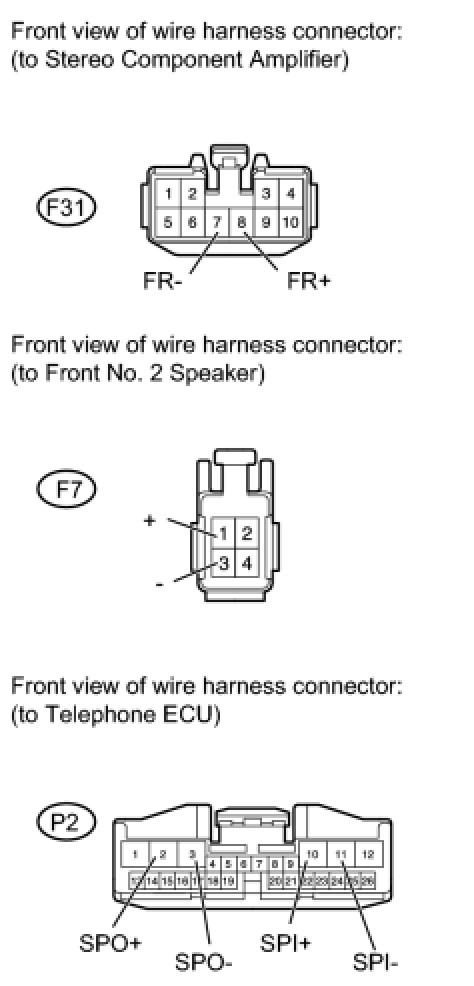
(a) Disconnect the F31 amplifier connector.
(b) Disconnect the F7 speaker connector.
(c) Disconnect the P2 ECU connector.
(d) Measure the resistance according to the value(s) in the table below.
Standard Resistance:
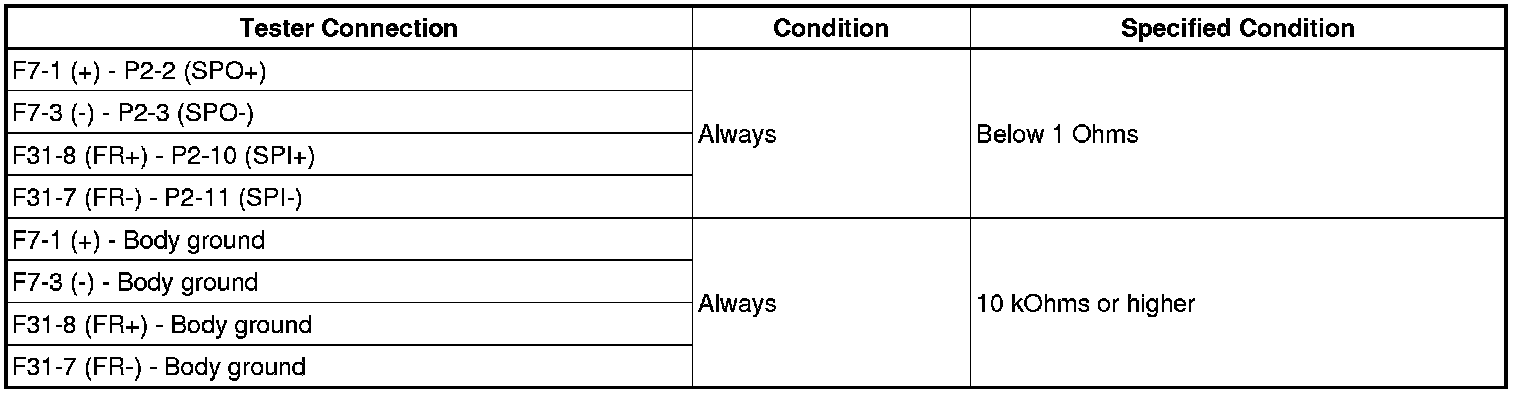
NG -- REPAIR OR REPLACE HARNESS OR CONNECTOR
OK -- Continue to next step.
9. CHECK STEREO COMPONENT AMPLIFIER ASSEMBLY (OPERATION)
(a) Replace the stereo component amplifier with a normal one and check that audio can be heard from the front RH side speaker Removal.
OK:
Audio can be heard.
NG -- REPLACE TELEPHONE ECU ASSEMBLY
OK -- END (STEREO COMPONENT AMPLIFIER IS DEFECTIVE)
10. CHECK HARNESS AND CONNECTOR (STEREO COMPONENT AMPLIFIER - FRONT NO. 2 SPEAKER)
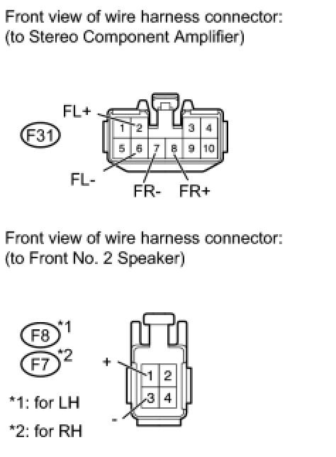
(a) Disconnect the F31 amplifier connector.
(b) Disconnect the F8 and F7 speaker connectors.
(c) Measure the resistance according to the value(s) in the table below.
Standard Resistance:
for LH

for RH

NG -- REPAIR OR REPLACE HARNESS OR CONNECTOR
OK -- REPLACE STEREO COMPONENT AMPLIFIER ASSEMBLY
11. INSPECT FRONT NO. 1 SPEAKER ASSEMBLY
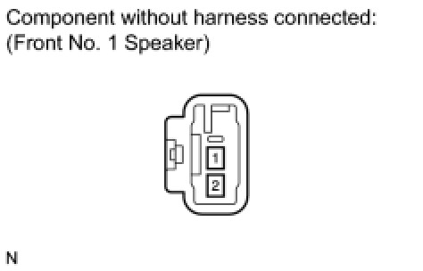
(a) Disconnect the I10 and I1 speaker connectors.
(b) Measure the resistance according to the value(s) in the table below.
Standard Resistance:

NG -- REPLACE FRONT NO. 1 SPEAKER ASSEMBLY
OK -- Continue to next step.
12. CHECK HARNESS AND CONNECTOR (STEREO COMPONENT AMPLIFIER - FRONT NO. 1 SPEAKER)
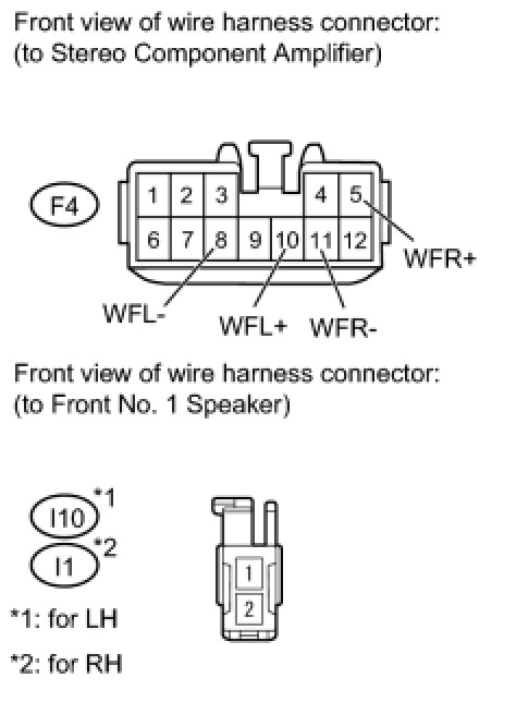
(a) Disconnect the I10 and I1 speaker connectors.
(b) Disconnect the F4 amplifier connector.
(c) Measure the resistance according to the value(s) in the table below.
Standard Resistance:
for LH

for RH

NG -- REPAIR OR REPLACE HARNESS OR CONNECTOR
OK -- REPLACE STEREO COMPONENT AMPLIFIER ASSEMBLY
13. CHECK FRONT NO. 3 SPEAKER ASSEMBLY
(a) Disconnect the F14 and F13 speaker connectors.
(b) Interchange the front No. 3 speaker LH with RH.
(c) Check that the malfunction disappears.
OK:
Malfunction disappears.
HINT:
- Connect all the connectors to the front No. 3 speakers.
- When there is a possibility that either the right or left front speaker is defective, inspect by interchanging the right one with the left one.
- Perform the inspection above on both the LH and RH sides.
NG -- INSPECT FRONT NO. 2 SPEAKER ASSEMBLY
OK -- REPLACE FRONT NO. 3 SPEAKER ASSEMBLY
14. INSPECT FRONT NO. 2 SPEAKER ASSEMBLY
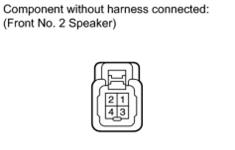
(a) Disconnect the F8 and F7 speaker connectors.
(b) Measure the resistance according to the value(s) in the table below.
Standard Resistance:

NG -- REPLACE FRONT NO. 2 SPEAKER ASSEMBLY
OK -- REPAIR OR REPLACE HARNESS OR CONNECTOR (FRONT NO. 2 SPEAKER - FRONT NO. 3 SPEAKER)
15. CHECK SPEAKER
(a) Check the malfunctioning speakers.
Result

E -- INSPECT REAR HEADER SPEAKER ASSEMBLY
D -- INSPECT NO. 1 WOOFER BOX SPEAKER ASSEMBLY
C -- INSPECT REAR SPEAKER SET
B -- CHECK REAR NO. 3 SPEAKER ASSEMBLY
A -- Continue to next step.
16. INSPECT REAR NO. 2 SPEAKER ASSEMBLY
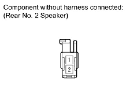
(a) Disconnect the rear No. 2 speaker connectors.
(b) Measure the resistance according to the value(s) in the table below.
Standard Resistance:

NG -- REPLACE REAR NO. 2 SPEAKER ASSEMBLY
OK -- REPLACE REAR NO. 3 SPEAKER ASSEMBLY
17. CHECK REAR NO. 3 SPEAKER ASSEMBLY
(a) Disconnect the rear No. 3 speaker connectors.
(b) Interchange the rear No. 3 speaker LH with RH.
(c) Check that the malfunction disappears.
OK:
Malfunction disappears.
HINT:
- Connect all the connectors to the rear No. 3 speakers.
- When there is a possibility that either the right or left rear speaker is defective, inspect by interchanging the right one with the left one.
- Perform the inspection above on both the LH and RH sides.
NG -- CHECK HARNESS AND CONNECTOR (STEREO COMPONENT AMPLIFIER - REAR NO. 3 SPEAKER)
OK -- REPLACE REAR NO. 3 SPEAKER ASSEMBLY
18. CHECK HARNESS AND CONNECTOR (STEREO COMPONENT AMPLIFIER - REAR NO. 3 SPEAKER)
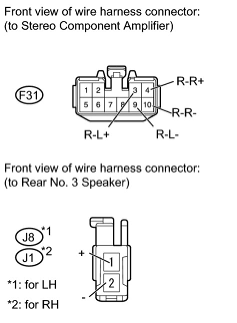
(a) Disconnect the F31 amplifier connector.
(b) Disconnect the J8 and J1 speaker connectors.
(c) Measure the resistance according to the value(s) in the table below.
Standard Resistance:
for LH

for RH

NG -- REPAIR OR REPLACE HARNESS OR CONNECTOR
OK -- REPLACE STEREO COMPONENT AMPLIFIER ASSEMBLY
19. INSPECT REAR SPEAKER SET
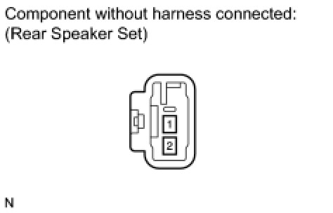
(a) Disconnect the J17 and J15 speaker connectors.
(b) Measure the resistance according to the value(s) in the table below.
Standard Resistance:

NG -- REPLACE REAR SPEAKER SET
OK -- Continue to next step.