Black Screen
AUDIO / VIDEO: REAR SEAT ENTERTAINMENT SYSTEM: Black Screen
Black Screen
INSPECTION PROCEDURE
PROCEDURE
1. CHECK TELEVISION DISPLAY ASSEMBLY (POWER)
(a) Check if the power of the television display is on.
OK:
Power is on.
NG -- TURN TELEVISION DISPLAY ASSEMBLY POWER ON
OK -- Continue to next step.
2. CHECK TELEVISION DISPLAY ASSEMBLY (OPENING ANGLE)
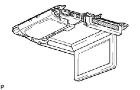
(a) Check if the television display is open 90° or more.
OK:
Open 90° or more.
HINT:
The television display tilt can be adjusted to 4 positions: 90°, 100°, 110° and 120°.
NG -- OPEN 90° OR MORE
OK -- Continue to next step.
3. CHECK MODE IN WHICH BLACK SCREEN OCCURRED
(a) Check the mode in which the black screen occurred.
Result

C -- CHECK HARNESS AND CONNECTOR (TELEVISION DISPLAY ASSEMBLY - BODY GROUND)
B -- CHECK HARNESS AND CONNECTOR (TELEVISION DISPLAY ASSEMBLY - BODY GROUND)
A -- Continue to next step.
4. CHECK DISPLAY SIGNAL CIRCUIT BETWEEN MULTI-DISPLAY AND TELEVISION DISPLAY ASSEMBLY
(a) Refer to the Display Signal Circuit between Multi-display and Television Display Display Signal Circuit Between Multi-Display And Television Display Assembly. If the display signal circuit is operating normally, proceed to the next step.
NEXT -- Continue to next step.
5. CHECK AVC-LAN CIRCUIT
(a) Refer to the AVC-LAN Circuit AVC-LAN Circuit. If the AVC-LAN circuit is operating normally, proceed to the next step.
NEXT -- REPLACE TELEVISION DISPLAY ASSEMBLY
6. CHECK HARNESS AND CONNECTOR (TELEVISION DISPLAY ASSEMBLY - BODY GROUND)
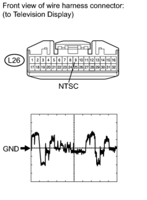
(a) Disconnect the L26 display connector.
(b) Check the waveform of the television display using an oscilloscope.
Measurement Condition

OK:
Waveform is as shown in the illustration.
NG -- DISPLAY SIGNAL CIRCUIT BETWEEN RADIO RECEIVER AND TELEVISION DISPLAY ASSEMBLY
OK -- REPLACE TELEVISION DISPLAY ASSEMBLY
7. DISPLAY SIGNAL CIRCUIT BETWEEN RADIO RECEIVER AND TELEVISION DISPLAY ASSEMBLY
(a) Refer to the Display Signal Circuit between Radio Receiver and Television Display Display Signal Circuit Between Radio Receiver And Television Display Assembly. If the display signal circuit is operating normally, proceed to the next step.
NEXT -- Continue to next step.
8. CHECK AVC-LAN CIRCUIT
(a) Refer to the AVC-LAN Circuit AVC-LAN Circuit. If the AVC-LAN circuit is operating normally, proceed to the next step.
NEXT -- REPLACE TELEVISION DISPLAY ASSEMBLY
9. CHECK HARNESS AND CONNECTOR (TELEVISION DISPLAY ASSEMBLY - BODY GROUND)
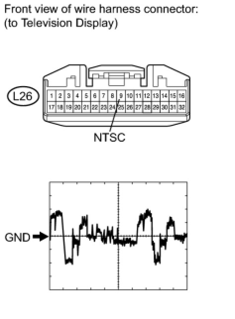
(a) Disconnect the L26 display connector.
(b) Check the waveform of the television display using an oscilloscope.
Measurement Condition

OK:
Waveform is as shown in the illustration.
NG -- CHECK DISPLAY SIGNAL CIRCUIT BETWEEN VIDEO TERMINAL AND TELEVISION DISPLAY
OK -- REPLACE TELEVISION DISPLAY ASSEMBLY
10. CHECK DISPLAY SIGNAL CIRCUIT BETWEEN VIDEO TERMINAL AND TELEVISION DISPLAY
(a) Refer to the Display Signal Circuit between Video Terminal and Television Display Display Signal Circuit between Video Terminal and Television Display. If the display signal circuit is operating normally, proceed to the next step.
NEXT -- Continue to next step.
11. CHECK AVC-LAN CIRCUIT
(a) Refer to the AVC-LAN Circuit AVC-LAN Circuit. If the AVC-LAN circuit is operating normally, proceed to the next step.
NEXT -- REPLACE TELEVISION DISPLAY ASSEMBLY