Airbag System
SUPPLEMENTAL RESTRAINT SYSTEMS: AIRBAG SYSTEM: B1660/43: Passenger Airbag ON/OFF Indicator Circuit Malfunction
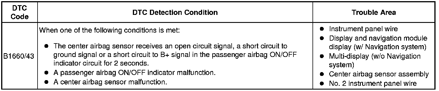
DTC B1660/43 - Passenger Airbag ON/OFF Indicator Circuit Malfunction
DESCRIPTION
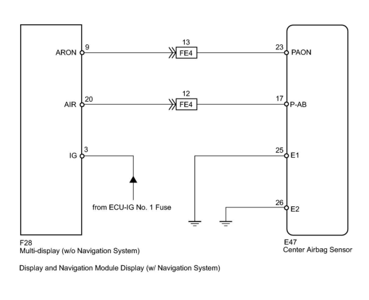
The passenger airbag ON/OFF indicator circuit consists of the center airbag sensor and the passenger airbag ON/OFF indicator.
The passenger airbag ON/OFF indicator indicates the operation condition of the front passenger airbag, front passenger side knee airbag, front seat side airbag RH and front seat outer belt RH.
DTC B1660/43 is stored when a malfunction is detected in the passenger airbag ON/OFF indicator circuit.
WIRING DIAGRAM
INSPECTION PROCEDURE
NOTICE:
- w/ Navigation system:
After the engine switch is turned off, the HDD navigation system requires approximately 6 minutes to record various types of memory and settings. As a result, after turning the engine switch off, wait 6 minutes or more before disconnecting the cable from the negative (-) battery terminal.
- When disconnecting the cable from the negative (-) battery terminal while performing repairs, some systems need to be initialized after the cable is reconnected Repair Instruction - Initialization.
PROCEDURE
1. CHECK PASSENGER AIRBAG ON/OFF INDICATOR CONDITION
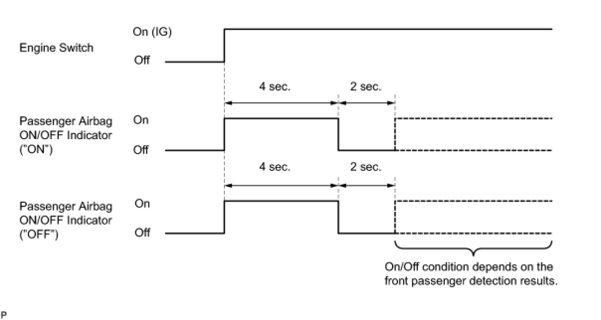
(a) Turn the engine switch on (IG).
(b) Check the passenger airbag ON/OFF indicator operation.
HINT:
Refer to the normal condition of the passenger airbag ON/OFF indicator Diagnosis System.
Result

B -- CHECK CONNECTION OF CONNECTORS
A -- Continue to next step.
2. CHECK CONNECTION OF CONNECTORS
(a) Turn the engine switch off.
(b) Disconnect the cable from the negative (-) battery terminal, and wait for at least 90 seconds.
(c) Check that the connectors are properly connected to the center airbag sensor and the multi-display or display and navigation module display.
OK:
The connectors are properly connected.
NG -- CONNECT CONNECTORS PROPERLY
OK -- Continue to next step.
3. CHECK CONNECTORS
(a) Disconnect the connectors from the center airbag sensor and the multi-display or display and navigation module display.
(b) Check that the connectors (on the center airbag sensor side and multi-display side or display and navigation module display side) are not damaged.
OK:
The connectors are not deformed or damaged.
NG -- REPLACE HARNESS AND CONNECTOR
OK -- Continue to next step.
4. CHECK PASSENGER AIRBAG ON/OFF INDICATOR
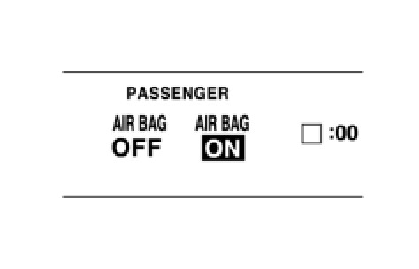
(a) Connect the connector to the multi-display or display and navigation module display.
(b) Connect the cable to the negative (-) battery terminal, and wait for at least 2 seconds.
(c) Turn the engine switch on (IG).
(d) Check the passenger airbag ON/OFF indicator operation.
OK:
The passenger airbag ON/OFF indicator does not come on.
NG -- CHECK PASSENGER AIRBAG ON/OFF INDICATOR CIRCUIT
OK -- Continue to next step.
5. CHECK CENTER AIRBAG SENSOR
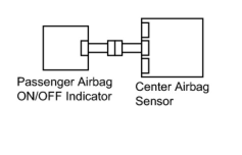
(a) Connect the connector to the center airbag sensor.
(b) Connect the cable to the negative (-) battery terminal, and wait for at least 2 seconds.
(c) Turn the engine switch on (IG), and wait for at least 60 seconds.
(d) Clear the DTCs DTC Check / Clear.
(e) Turn the engine switch off.
(f) Turn the engine switch on (IG), and wait for at least 60 seconds.
(g) Check for DTCs DTC Check / Clear.
OK:
DTC B1660 is not output.
HINT:
Codes other than DTC B1660 may be output at this time, but they are not related to this check.
NG -- REPLACE CENTER AIRBAG SENSOR ASSEMBLY
OK -- USE SIMULATION METHOD TO CHECK
6. CHECK PASSENGER AIRBAG ON/OFF INDICATOR CIRCUIT
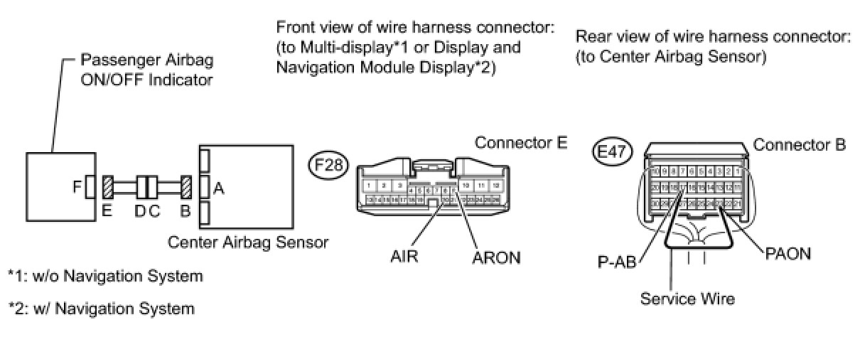
(a) Turn the engine switch off.
(b) Disconnect the cable from the negative (-) battery terminal, and wait for at least 90 seconds.
(c) Disconnect the connector from the center airbag sensor and multi-display or display and navigation module display.
(d) Connect the cable to the negative (-) battery terminal, and wait for at least 2 seconds.
(e) Measure the voltage according to the value(s) in the table below.
Standard Voltage:

(f) Turn the engine switch off.
(g) Disconnect the cable from the negative (-) battery terminal, and wait for at least 90 seconds.
(h) Using a service wire, connect terminals 23 (PAON) and 17 (P-AB) of connector B.
NOTICE:
Do not forcibly insert the service wire into the terminals of the connector when connecting a service wire.
(i) Measure the resistance according to the value(s) in the table below.
Standard Resistance:

(j) Disconnect the service wire from connector B.
(k) Measure the resistance according to the value(s) in the table below.
Standard Resistance:

Result

C -- REPLACE DISPLAY AND NAVIGATION MODULE DISPLAY
B -- REPLACE MULTI-DISPLAY
A -- Continue to next step.
7. CHECK INSTRUMENT PANEL WIRE (CENTER AIRBAG SENSOR - NO. 2 INSTRUMENT PANEL WIRE)
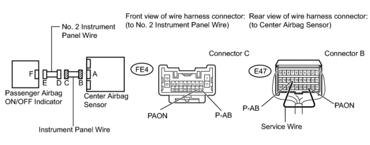
(a) Disconnect the instrument panel wire connector from the No. 2 instrument panel wire.
(b) Connect the cable to the negative (-) battery terminal, and wait for at least 2 seconds.
(c) Measure the voltage according to the value(s) in the table below.
Standard Voltage:

(d) Turn the engine switch off.
(e) Disconnect the cable from the negative (-) battery terminal, and wait for at least 90 seconds.
(f) Using a service wire, connect terminals 23 (PAON) and 17 (P-AB) of connector B.
NOTICE:
Do not forcibly insert the service wire into the terminals of the connector when connecting a service wire.
(g) Measure the resistance according to the value(s) in the table below.
Standard Resistance:

(h) Disconnect the service wire from connector B.
(i) Measure the resistance according to the value(s) in the table below.
Standard Resistance:

NG -- REPLACE INSTRUMENT PANEL WIRE
OK -- REPLACE NO. 2 INSTRUMENT PANEL WIRE
8. CHECK CONNECTION OF CONNECTORS
(a) Turn the engine switch off.
(b) Disconnect the cable from the negative (-) battery terminal, and wait for at least 90 seconds.
(c) Check that the connectors are properly connected to the center airbag sensor and the multi-display or display and navigation module display.
OK:
The connectors are properly connected.
NG -- CONNECT CONNECTORS PROPERLY
OK -- Continue to next step.
9. CHECK CONNECTORS
(a) Disconnect the connectors from the center airbag sensor and the multi-display or display and navigation module display.
(b) Check that the connectors (on the center airbag sensor side and multi-display side or display and navigation module display side) are not damaged.
OK:
The connectors are not deformed or damaged.
NG -- REPLACE HARNESS AND CONNECTOR
OK -- Continue to next step.
10. CHECK PASSENGER AIRBAG ON/OFF INDICATOR CIRCUIT
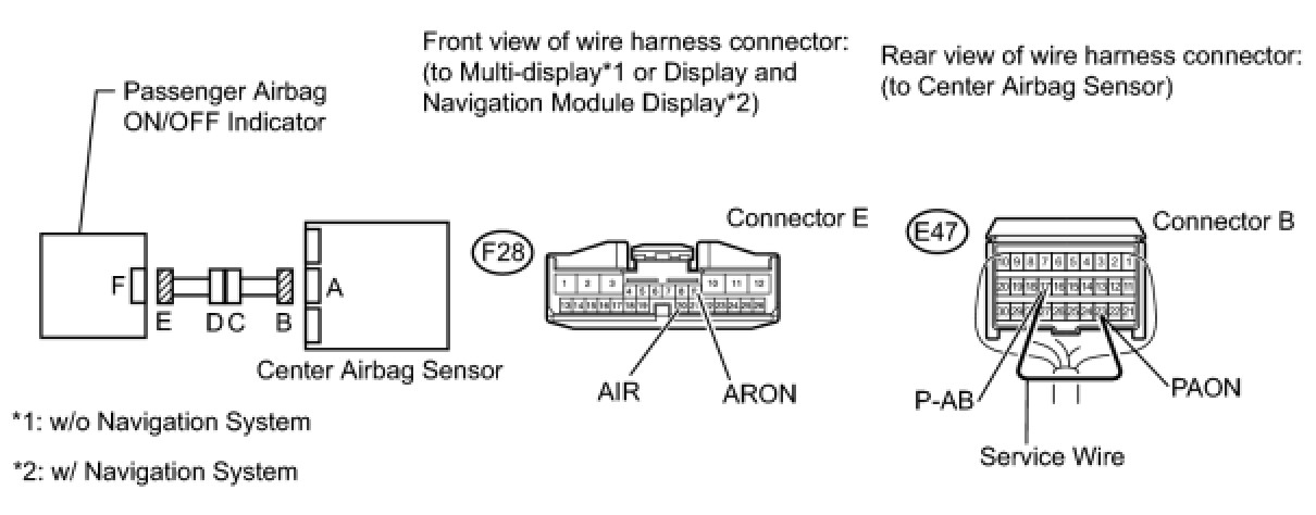
(a) Connect the cable to the negative (-) battery terminal, and wait for at least 2 seconds.
(b) Measure the voltage according to the value(s) in the table below.
Standard Voltage:

(c) Turn the engine switch off.
(d) Disconnect the cable from the negative (-) battery terminal, and wait for at least 90 seconds.
(e) Using a service wire, connect terminals 23 (PAON) and 17 (P-AB) of connector B.
NOTICE:
Do not forcibly insert the service wire into the terminals of the connector when connecting a service wire.
(f) Measure the resistance according to the value(s) in the table below.
Standard Resistance:

(g) Disconnect the service wire from connector B.
(h) Measure the resistance according to the value(s) in the table below.
Standard Resistance:

NG -- CHECK INSTRUMENT PANEL WIRE (CENTER AIRBAG SENSOR - NO. 2 INSTRUMENT PANEL WIRE)
OK -- Continue to next step.
11. CHECK PASSENGER AIRBAG ON/OFF INDICATOR (SOURCE VOLTAGE)
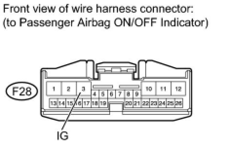
(a) Turn the engine switch off.
(b) Connect the connectors to the center airbag sensor.
(c) Connect the cable to the negative (-) battery terminal, and wait for at least 2 seconds.
(d) Measure the voltage according to the value(s) in the table below.
Standard Voltage:

NG -- REPLACE HARNESS AND CONNECTOR (DISPLAY - BATTERY) OR BATTERY
OK -- Continue to next step.
12. CHECK PASSENGER AIRBAG ON/OFF INDICATOR
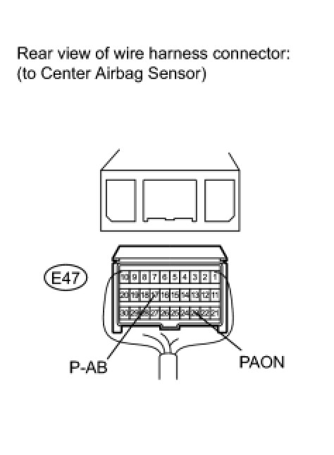
(a) Turn the engine switch off.
(b) Disconnect the cable from the negative (-) battery terminal, and wait for at least 90 seconds.
(c) Connect the connector to the multi-display or display and navigation module display.
(d) Disconnect the connectors from the center airbag sensor.
(e) Connect the cable to the negative (-) battery terminal, and wait for at least 2 seconds.
(f) Check the indicator according to the value(s) in the table below.
OK:

Result

C -- REPLACE MULTI-DISPLAY
B -- REPLACE DISPLAY AND NAVIGATION MODULE DISPLAY
A -- Continue to next step.
13. CHECK CENTER AIRBAG SENSOR
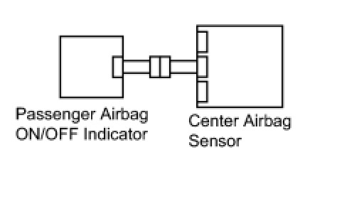
(a) Turn the engine switch off.
(b) Disconnect the cable from the negative (-) battery terminal, and wait for at least 90 seconds.
(c) Connect the connectors to the center airbag sensor.
(d) Connect the cable to the negative (-) battery terminal, and wait for at least 2 seconds.
(e) Turn the engine switch on (IG), and wait for at least 60 seconds.
(f) Clear the DTCs DTC Check / Clear.
(g) Turn the engine switch off.
(h) Turn the engine switch on (IG), and wait for at least 60 seconds.
(i) Check for DTCs DTC Check / Clear.
OK:
DTC B1660 is not output.
HINT:
Codes other than DTC B1660 may be output at this time, but they are not related to this check.
NG -- REPLACE CENTER AIRBAG SENSOR ASSEMBLY
OK -- USE SIMULATION METHOD TO CHECK
14. CHECK INSTRUMENT PANEL WIRE (CENTER AIRBAG SENSOR - NO. 2 INSTRUMENT PANEL WIRE)
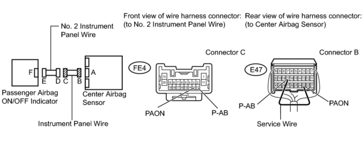
(a) Disconnect the instrument panel wire connector from the No. 2 instrument panel wire.
(b) Connect the cable to the negative (-) battery terminal, and wait for at least 2 seconds.
(c) Measure the voltage according to the value(s) in the table below.
Standard Voltage:

(d) Turn the engine switch off.
(e) Disconnect the cable from the negative (-) battery terminal, and wait for at least 90 seconds.
(f) Using a service wire, connect terminals 23 (PAON) and 17 (P-AB) of connector B.
NOTICE:
Do not forcibly insert the service wire into the terminals of the connector when connecting a service wire.
(g) Measure the resistance according to the value(s) in the table below.
Standard Resistance:

(h) Disconnect the service wire from connector B.
(i) Measure the resistance according to the value(s) in the table below.
Standard Resistance:

NG -- REPLACE INSTRUMENT PANEL WIRE
OK -- REPLACE NO. 2 INSTRUMENT PANEL WIRE