Instrument Panel Safety Pad: Reassembly
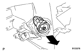
- INSTALL INSTRUMENT PANEL SPACER
 Courtesy of © TOYOTA, LICENSE AGREEMENT TMS1002
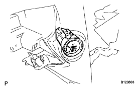
- INSTALL ENGINE SWITCH
- Engage the 2 claws and install the engine switch.
 Courtesy of © TOYOTA, LICENSE AGREEMENT TMS1002
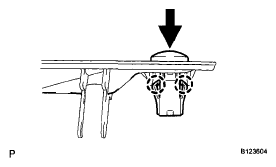
- INSTALL AUTOMATIC LIGHT CONTROL SENSOR
- Engage the 2 claws and install the automatic light control sensor.
 Courtesy of © TOYOTA, LICENSE AGREEMENT TMS1002
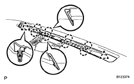
- INSTALL DEFROSTER NOZZLE GARNISH
- Engage the 8 claws and 2 clips, and install the defroster nozzle garnish.
 Courtesy of © TOYOTA, LICENSE AGREEMENT TMS1002
- INSTALL FRONT PASSENGER AIRBAG ASSEMBLY
(See
INSTALLATION
)
- INSTALL NO. 2 INSTRUMENT PANEL WIRE
- Engage the 5 clamps.
- Connect the connector and install the No. 2 instrument panel wire.
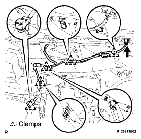 Courtesy of © TOYOTA, LICENSE AGREEMENT TMS1002
- INSTALL NAVIGATION ANTENNA
(See
INSTALLATION
)
- INSTALL NO. 2 ANTENNA CORD SUB-ASSEMBLY
(See
INSTALLATION
)
- INSTALL SIDE DEFROSTER NOZZLE
- Engage the 4 claws and install the side defroster nozzle.
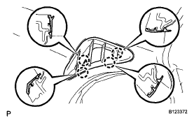 Courtesy of © TOYOTA, LICENSE AGREEMENT TMS1002
- INSTALL NO. 2 HEATER TO REGISTER DUCT
- Install the No. 2 heater to register duct with the 4 screws < F >.
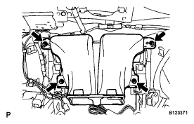 Courtesy of © TOYOTA, LICENSE AGREEMENT TMS1002
- INSTALL DEFROSTER NOZZLE ASSEMBLY
- Install the defroster nozzle assembly with the 3 screws < F >.
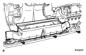 Courtesy of © TOYOTA, LICENSE AGREEMENT TMS1002
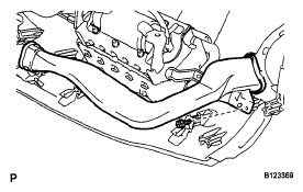
- INSTALL SIDE NO. 2 DEFROSTER NOZZLE DUCT
- Install the side No. 2 defroster nozzle duct with the screw < F >.
 Courtesy of © TOYOTA, LICENSE AGREEMENT TMS1002
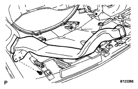
- INSTALL SIDE NO. 1 DEFROSTER NOZZLE DUCT
- Install the side No. 1 defroster nozzle duct with the screw < F >.
 Courtesy of © TOYOTA, LICENSE AGREEMENT TMS1002
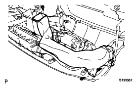
- INSTALL NO. 3 HEATER TO REGISTER DUCT
- Install the No. 3 heater to register duct with the 3 screws < F >.
 Courtesy of © TOYOTA, LICENSE AGREEMENT TMS1002
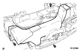
- INSTALL NO. 1 HEATER TO REGISTER DUCT
- Install the No. 1 heater to register duct with the 3 screws < F >.
 Courtesy of © TOYOTA, LICENSE AGREEMENT TMS1002