Cooling Fan Relay No. 2
- Relays are marked FAN No. 1, FAN No. 2 and FAN No. 3. See COMPONENT LOCATIONS . Ensure continuity is present between relay terminals No. 3 and 5. See Fig 1. Ensure there is no continuity between relay terminals No. 1 and 2. Ensure there is continuity between terminals No. 2 and 4. If continuity measurements are not to specification, replace cooling fan relay. If continuity exists as described, go to next step.
- Apply battery voltage across relay terminals No. 3 and 5. There should be no continuity between terminals No. 2 and 4. There should be continuity between terminals No. 1 and 2. Replace relay as necessary.
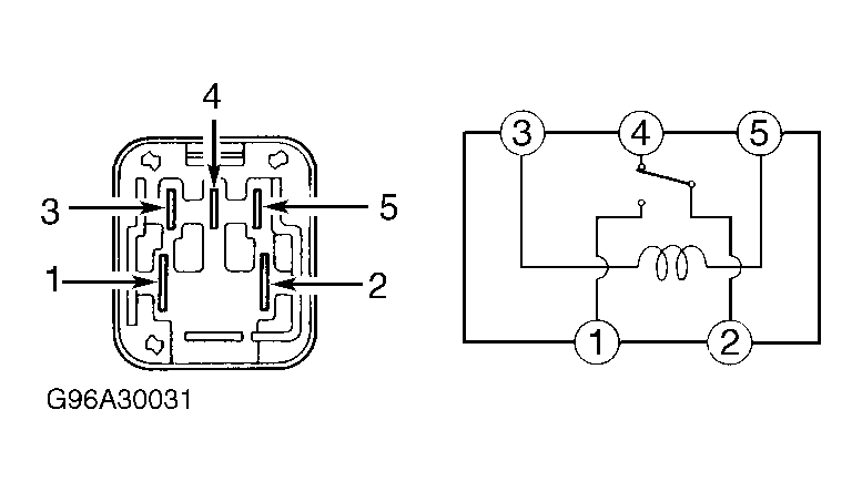 Courtesy of © TOYOTA, LICENSE AGREEMENT TMS1002