Gear Change/Selector Housings - Overhaul
Gear Change/Selector Housings - Overhaul
Gear change housing - Type A gearbox
Dismantle
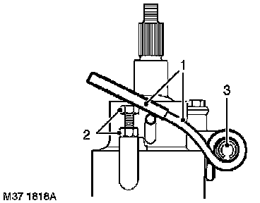
1. Using a suitable piece of tubing, release both ends of bias spring from ball pins.
2. Slacken locknuts and remove bias spring adjusting screws.
3. Drift out roll pin, remove bias spring.
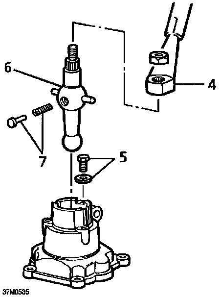
4. Remove extension from lower gear lever.
5. Remove bolt and special washer securing lower gear lever.
6. Carefully withdraw lower gear lever from housing ensuring that spring loaded nylon pad is retained during removal.
WARNING: personal injury may result if pad is not retained.
7. Release nylon pad, recover spring.
8. Clean all components.
Inspection
1. Check lower gear lever ball pin for wear, replace if necessary.
CAUTION: If lower gear lever is to be & replaced then bail pin seating, located in remote housing should also be replaced.
2. Check nylon pad and spring for wear and damage, replace if necessary.
3. Check bias spring roll pin for damage, replace if necessary.
Reassemble
1. Smear ball pin with multi-purpose grease and fit spring and nylon pad.
2. Depress nylon pad against spring pressure, position lower gear lever in housing.
CAUTION: Ensure nylon pad is facing away from bias spring location.
3. Fit lower gear lever retaining bolt and special washer, tighten bolt to 15 Nm (11 ft. lbs.).
4. Fit extension to lower gear lever.
5. Position roll pin and bias spring to housing, fit roll pin.
6. Fit bias spring adjusting screws and locknuts.
7. Using a suitable piece of tubing locate both ends of bias spring over ball pins.
NOTE: Do not adjust bias spring at this stage.
Remote housing - Type A gearbox
Dismantle
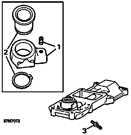
1. Remove setscrew securing trunnion to selector shaft, remove trunnion.
2. Remove and discard circlip securing ball pin seating to trunnion, remove seating.
3. Loosen locknut, remove 5th gear stop screw.
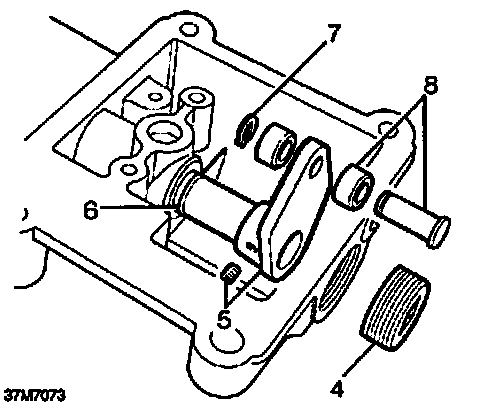
4. Remove blanking plug from end of remote housing.
5. Remove setscrew securing quadrant to selector shaft, remove quadrant.
NOTE: Early gearboxes: Quadrant is secured by a roll pin.
6. Remove selector shaft from remote housing, remove and discard '0' ring.
7. Remove and discard circlip retaining rollers and pin to quadrant.
8. Remove pin, recover rollers.
9. Clean all components.
Inspection
1. Check selector shaft and bore in remote housing for wear.
2. Check quadrant rollers and pin for wear.
3. Check ball pin seating for wear.
4. Replace worn components as necessary.
Reassemble
1. Lubricate selector shaft and new '0' ring with gearbox oil.
2. Fit '0' ring to selector shaft.
3. Fit shaft to remote housing.
4. Position rollers to quadrant, fit pin and secure with new circlip.
CAUTION: Ensure that head of pin is on & opposite side of quadrant to selector shaft boss.
5. Fit quadrant to selector shaft.
6. Apply Loctite 290 to threads of setscrew, fit setscrew and tighten to 25 Nm (18 ft. lbs.).
NOTE: Early gearboxes: Fit new roll pin.
7. Apply Loctite 290 to threads of blanking plug, fit plug and tighten to 30 Nm (22 ft. lbs.).
8. Smear ball pin seating with multi-purpose grease.
9. Position ball pin seating in trunnion, secure with a new circlip.
10. Position trunnion on selector shaft.
11. Apply Loctite 290 to threads of setscrew, fit setscrew and tighten to 25 Nm (18 ft. lbs.).
12. Fit 5th gear stop screw, fit but do not tighten locknut.
NOTE: 5th gear stop screw adjustment is carried out during gearbox reassembly.
Gear change housing - Type B gearbox
Dismantle
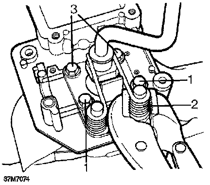
1. Remove bolts retaining bias springs.
WARNING: To avoid personal injury, restrain each spring in turn with a pair of grips while the bolts are being removed.
2. Remove the two bias springs.
3. Remove 2 bolts securing bias spring adjustment plate.
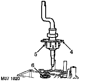
4. Lift lower lever assembly out of gear change housing.
5. Remove and discard Railko bush.
6. Remove and discard oil seal from housing.
7. Clean all components.
Inspection
1. Check ball cross pin slots in gear change housing for wear.
2. Check ball and pins for wear.
3. Check bias springs for distortion.
4. Replace worn components as necessary.
Reassemble
1. Apply multi-purpose grease to ball and cross pins.
2. Apply multi-purpose grease to new Railko bush and fit to gear change housing.
CAUTION: Ensure that the slots in each & bush are aligned with slots in housing.
3. Lubricate a new oil seal with gearbox oil.
4. Fit oil seal, lip side towards housing, using a suitable mandrel.
5. Position gear lever to gear change housing ensuring ball cross pins are located in slots in housing and Railko bush.
6. Position bias spring adjustment plate to gear change housing.
7. Apply Loctite 290 to threads of 2 short bias spring adjustment plate bolts.
8. Fit bolts to secure front of bias adjustment plate and tighten to 25 Nm (18 ft. lbs.).
9. Position bias spring to pillar ensuring longest end of spring is against gear lever.
10. Apply Loctite 290 to threads of 2 long bias adjustment plate bolts.
11. Restrain bias spring using a suitable pair of grips, ensure short end of bias spring is positioned on outside edge of bolt hole.
WARNING: personal injury may result if bias spring is not retained.
12. Fit bolt and washer ensuring end of bias spring is restrained beneath washer; tighten bolt to 25 Nm (18 ft. lbs.).
13. Repeat above procedures for remaining bias spring.
Remote gear change - Type C gearbox
Dismantle
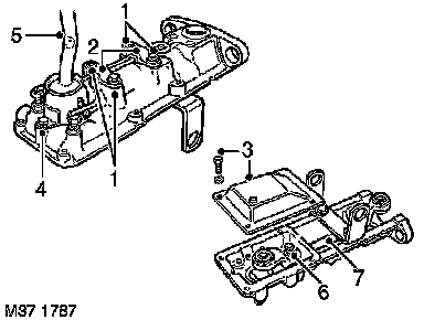
1. Remove 2 bolts and 2 countersunk screws securing bias spring bridge plates.
2. Remove bridge plates, bridge plate liners and bias spring.
3. Remove 4 bolts and washers securing bottom cover plate, remove plate.
4. Remove bolt securing gear lever cap, remove cap.
5. Remove gear lever, recover anti-rattle spring and plunger.
6. Remove pinch bolt securing selector rod yoke, remove yoke.
7. Withdraw selector rod from remote housing.
8. Clean all components.
Inspection
1. Check selector rod bushes in remote housing for wear.
NOTE: Bushes may be pressed in and out of remote housing using a hand press and suitable mandrel.
2. Check selector rod for wear, replace if necessary.
3. Check anti-rattle spring for distortion and plunger for wear; replace if necessary.
4. Check gear lever ball pin, cross pins, bushes and selector rod yoke balls for wear and replace if necessary. If yoke balls are worn, remove and discard circlip, press ball and seating out of yoke.
5. Lubricate replacement ball and seating with multi-purpose grease and press into yoke; secure using new circlip.
6. Check bias spring for distortion, replace if necessary.
7. Check condition of mounting rubbers, replace as a set if necessary.
Reassemble
1. Lubricate selector rod and bushes with multi -purpose grease, insert rod in remote housing.
2. Lubricate gear lever ball pin and selector rod yoke balls with multi-purpose grease.
3. Fit yoke to selector rod, fit pinch bolt and tighten to 25 Nm (18 ft. lbs.).
4. Assemble anti-rattle spring and plunger to gear lever.
5. Fit gear lever ensuring ball pin is located in yoke and anti-rattle spring and plunger are not displaced.
6. Fit gear lever cap, fit bolt and tighten to 15 Nm (11 ft. lbs.).
NOTE: Do not fit bottom cover plate at this stage.
7. Loosen bias spring adjustment bolt locknuts.
8. Fit bias spring, bridge plate liners and bridge plates.
9. Fit bolts and countersunk screws and tighten to 25 Nm (18ft. lbs.).
NOTE: Final adjustment of bias spring is carried out after remote gear change is fitted to gearbox.
Remote gear change - Type D gearbox
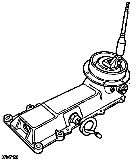
NOTE: With the exception of the reverse light switch, the remote gear change fitted to type D gearboxes is not a repairable item. It must be replaced if components are found to be worn.
Transfer box selector housing - Type A gearbox -Overhaul
Dismantle
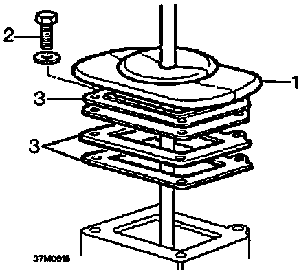
1. Slide gaiter off gear lever.
2. Remove 4 bolts securing gaiter support plate and gate plate.
3. Remove gaiter support plate and gate plate, discard gaskets.
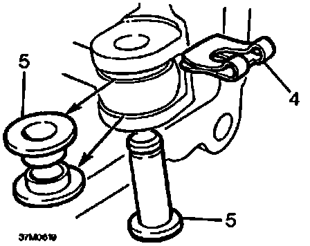
4. Remove and discard spring clip retaining selector fork clevis pin.
5. Remove clevis pin from selector fork, remove and discard 2 bushes.
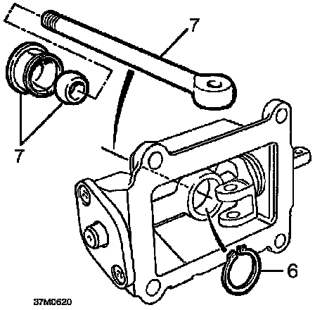
6. Remove and discard circlip retaining nylon ball seating.
7. Remove gear lever, recover nylon seating and ball.
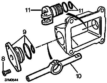
8. Remove 2 countersunk head screws securing end cover to housing.
9. Remove end cover, remove and discard 2 '0' rings.
10. Withdraw cross shaft.
11. Remove selector fork, remove and discard 2 '0' rings.
12. Clean all components.
Inspection
1. Check gaiter for splits and damage.
2. Check nylon seating and ball for wear, replace if necessary.
CAUTION: Seating and ball should be renewed as an assembly.
3. Check selector fork and clevis pin for wear.
4. Check cross shaft and end cover for wear.
5. Replace components as necessary.
Reassemble
1. Lubricate new '0' rings with gearbox oil and fit to selector fork, position fork in housing.
2. Lubricate cross shaft with multi-purpose grease and locate longest end of shaft in selector fork.
3. Lubricate new '0' rings with gearbox oil and fit to end cover.
4. Position end cover on cross shaft, fit and tighten countersunk screws.
5. Assemble ball and nylon seating to gear lever ensuring that groove in seating is towards cross shaft.
6. Lubricate ball and nylon seating with multi -purpose grease and locate in cross shaft; retain with a new circlip.
7. Position new bushes to gear lever, locate in selector fork and fit clevis pin.
8. Fit new spring clip to retain clevis pin.
9. Position gate plate and gaiter support plate to housing, use new gaskets.
10. Fit retaining bolts and tighten to 15 Nm (11 ft. lbs.).
11. Fit gaiter.