Speedometer Test: Sephia
- Remove instrument cluster. See INSTRUMENT CLUSTER under REMOVAL & INSTALLATION. Disconnect instrument cluster 14-pin connector (C229) and 12-pin connector (C230). See Figure and Fig 1
. Check for continuity to ground at 14-pin connector terminal No. 10 (Yellow wire), 12-pin connector terminal No. 3 (Orange/Black wire) and terminal No. 8 (Green/Orange wire). If continuity exists, repair or replace appropriate wire. If continuity does not exist, go to next step.
- Reconnect instrument cluster connectors. Check that continuity to ground exists at 14-pin connector terminal No. 3 (Black wire). If continuity does not exist, repair or replace wire. If continuity to ground exists at terminal No. 3, go to next step.
- Disconnect VSS connector. Use a jumper wire to jump VSS connector Yellow wire and Green/Orange wire. Check that continuity exists between instrument cluster 12-pin connector terminal No. 3 (Orange/Black wire) and terminal No. 8 (Green/Orange wire). If continuity does not exist, repair wiring harness as necessary. If reading indicates continuity, remove jumper wire from VSS and go to next step.
- Remove VSS and inspect drive gear for damaged or missing teeth. Replace if necessary. Ensure VSS spins freely by hand. If oscilloscope is available, reconnect VSS connector, turn ignition on and monitor Green/Orange wire for square wave pattern while spinning VSS. If square wave pattern is present, replace speedometer. If square wave pattern is not present, replace VSS.
- If oscilloscope is not available, replace VSS with known-good unit and spin VSS drive gear. If vehicle speed is not seen at speedometer, replace speedometer. If vehicle speed is seen with known-good unit, replace VSS.
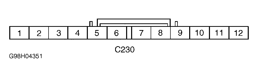 Courtesy of KIA MOTORS AMERICA, INC.