Right
RIGHT
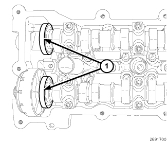
CAUTION: The magnetic timing wheels (1) must not come in contact with magnets (pickup tools, trays, etc.) or any other strong magnetic field. This will destroy the timing wheels ability to correctly relay camshaft position to the camshaft position sensor.
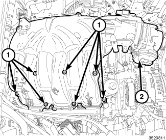
1. Disconnect and isolate the negative battery cable.
2. Remove the air cleaner body and upper intake manifold (2) .
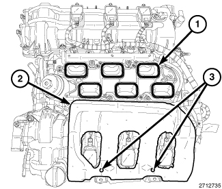
3. Cover the open intake ports (1) to prevent debris from entering the engine.
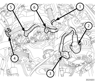
NOTE: Mark the variable valve timing solenoid connectors (5 and 6) with a paint pen or equivalent so that they may be reinstalled in their original locations.
4. Disconnect the right exhaust variable valve timing solenoid electrical connector (5).
5. Disconnect the right intake variable valve timing solenoid electrical connector (6).
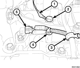
6. Disengage the wire harness retainers (1 and 4) from the right cylinder head cover.
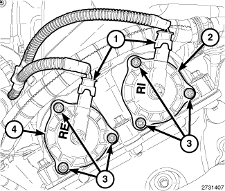
7. Mark the variable valve timing solenoids (2 and 4) with a paint pen or equivalent so that they may be reinstalled in their original locations.
8. Remove the variable valve timing solenoids
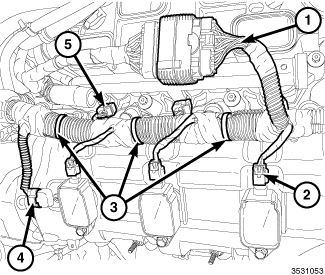
9. Disconnect three ignition coil electrical connectors (2).
10. Disconnect the electrical connector (4) from the right Camshaft Position (CMP) sensor.
11. Disengage three main wire harness retainers (3) from the right cylinder head cover.
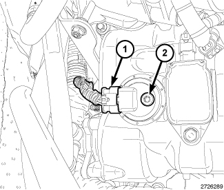
NOTE: If removing both RH and LH CMP sensors, mark the sensors so they can be installed in their original locations.
12. Remove the camshaft position sensor
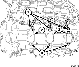
NOTE: The LH ignition coils are shown, the RH ignition coils are similar.
13. Remove the ignition coils (2)
14. Raise and support the vehicle Maintenance.
15. Disengage the main wire harness retainer (3) from the oil level indicator.
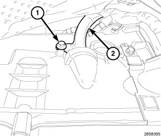
16. Loosen the bolt (1) securing the transmission fluid level indicator tube (2) to the transmission housing.
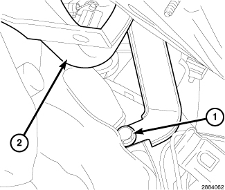
17. Remove the upper transmission to engine bolt (1) and reposition the transmission oil level indicator tube (2).
18. Lower the vehicle.
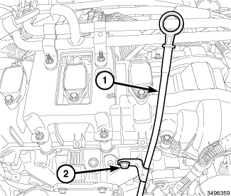
19. Remove the bolt (2) and the oil level indicator (1).
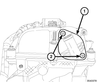
20. Remove the PCV valve (1)

21. Loosen nine cylinder head cover mounting bolts (1) and three studbolts (2) and remove the cylinder head cover.
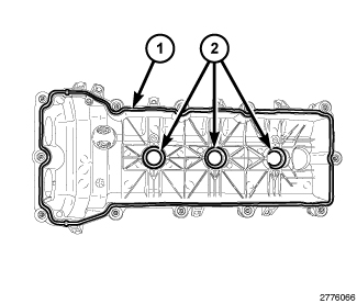
NOTE: The LH cylinder head cover is shown, the RH cylinder head cover is similar.
22. Remove and discard the cylinder head cover gasket (1).
23. The spark plug tube seals (2) can be reused if not damaged.
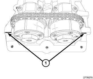
NOTE: The LH cylinder head cover T-joints are shown, the RH cylinder head cover T-joints are similar.
CAUTION: Do not use oil based liquids, wire brushes, abrasive wheels or metal scrapers to clean the engine gasket surfaces. Use only isopropyl (rubbing) alcohol, along with plastic or wooden scrapers. Improper gasket surface preparation may result in engine fluid leakage.
24. Remove all residual sealant (1) from the cylinder head, timing chain cover and cylinder head cover mating surfaces Procedures