P0931
P0931-BTSI CONTROL CIRCUIT HIGH
For a complete wiring diagram, refer to the Wiring Information.
Theory of Operation
The brake switch signal must be active before the shift lever can be moved out of the park position. The Shift Lever Assembly (SLA) Electronic Shift Module (ESM) receives two brake switch signals. The first signal is a CAN C Bus message sent to the shifter lever assembly. The second signal is a hard wired brake switch signal to the shifter lever assembly. The CAN C Bus message is the primary brake switch signal and the hard wired signal serves as the backup brake switch signal. These two brake switch signals are compared against each other to verify proper brake switch operation.
- When Monitored:
Continuously with the ignition in the run position.
- Set Condition:
The DTC will set if the high side driver detects an open load for 10 seconds.

Always perform the NAG1 Pre-Diagnostic Troubleshooting procedure before proceeding. Initial Inspection and Diagnostic Overview.
1. PCM DTCs PRESENT
1. With the scan tool, read PCM DTCs.
Are there any PCM brake DTCs present?
Yes
- Testing and Inspection perform the appropriate diagnostic procedure.
No
- Go To 2
2. ABS MODULE DTCs PRESENT
1. With the scan tool, read ABS Module DTCs.
Are there any ABS DTCs present?
Yes
- Testing and Inspection perform the appropriate diagnostic procedure.
No
- Go To 3
3. (L51) BRAKE SWITCH SIGNAL OPEN
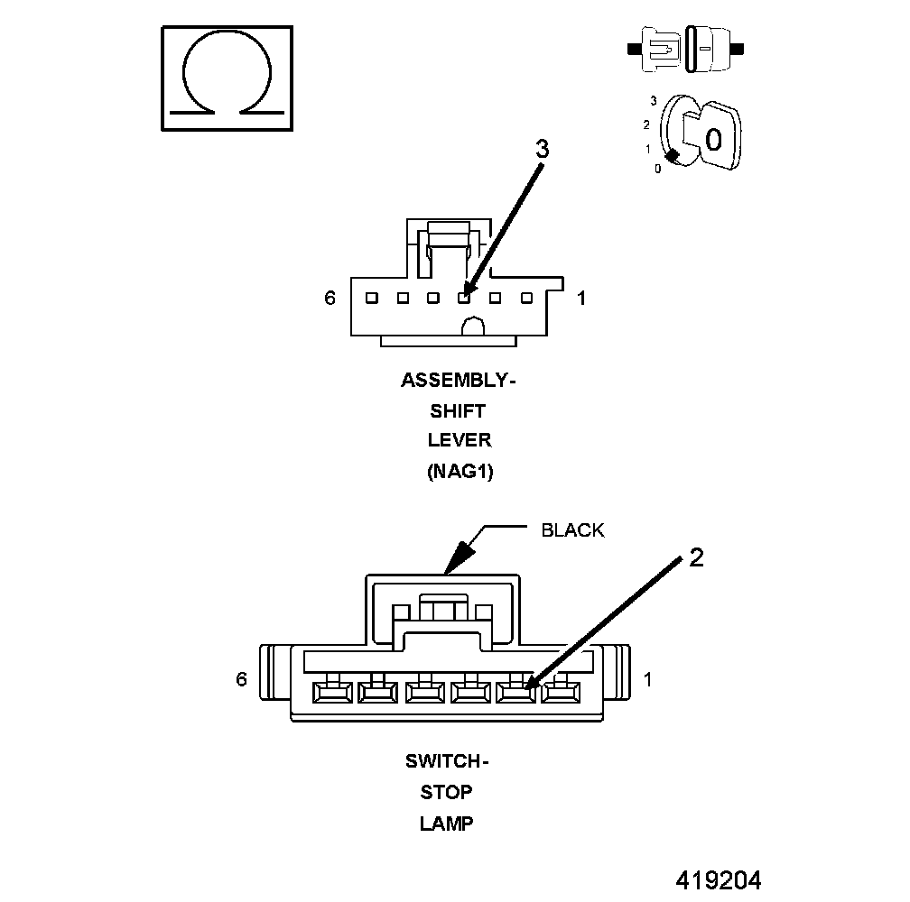
1. Turn the ignition off to the lock position.
2. Disconnect the Shift Lever Assembly harness connector.
3. Disconnect the Stop Lamp Switch harness connector.
NOTE: Check connectors - Clean/repair as necessary.
4. Measure the resistance of the (L51) Brake Switch Signal circuit between the Shift Lever Assembly harness connector and the Stop Lamp Switch.
Is the resistance above 5.0 Ohms?
Yes
- Repair the (L51) Brake Switch Signal for an open.
- Perform the NAG1 TRANSMISSION VERIFICATION TEST. NAG1 Transmission Verification Test.
No
- Go To 4
4. (L51) BRAKE SWITCH SIGNAL SHORTED TO VOLTAGE
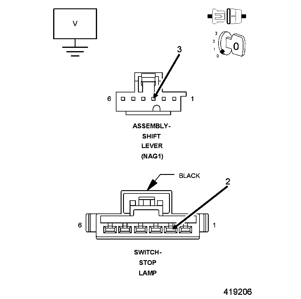
1. Turn the ignition off to the lock position.
2. Disconnect the Shift Lever Assembly harness connector.
NOTE: Check connectors - Clean/repair as necessary.
3. Turn the ignition on.
4. Measure the voltage of the (L51) Brake Switch Signal circuit.
Is the voltage above 0.5 of a volt?
Yes
- Repair the (L51) Brake Switch Signal for a short to voltage.
- Perform the NAG1 TRANSMISSION VERIFICATION TEST. NAG1 Transmission Verification Test.
No
- Replace the Shift Lever Assembly.
- Perform the NAG1 TRANSMISSION VERIFICATION TEST. NAG1 Transmission Verification Test.