Panel, Instrument: Removal: Removal
 Courtesy of CHRYSLER GROUP, LLC
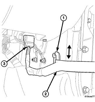
- Disconnect the electrical connector (3) at the A-pillar cowl area and separate the check strap (2) from the footmans loop (1).
- Open the doors past 90°, to aid in the removal of the I/P assembly.
 Courtesy of CHRYSLER GROUP, LLC
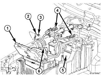
- Disconnect and isolate the negative battery cable.
- Remove the center console. Refer to CONSOLE, CENTER, REMOVAL .
 Courtesy of CHRYSLER GROUP, LLC
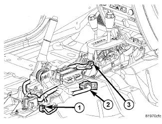
- Disconnect the center I/P wire harness electrical connectors (1, 2 and 3).
 Courtesy of CHRYSLER GROUP, LLC
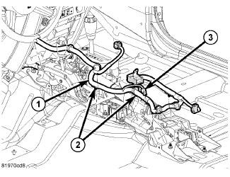
- Release the push pin hangers (2) and position aside the harness (1).
- Remove the steering column opening cover. Refer to COVER, STEERING COLUMN OPENING, REMOVAL .
- Remove the amplifier. Refer to AMPLIFIER, REMOVAL
.
- Remove the steering column as necessary. Refer to COLUMN, REMOVAL
.
 Courtesy of CHRYSLER GROUP, LLC
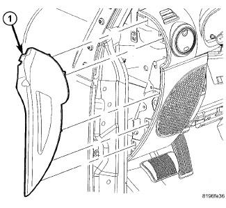
- Using a trim stick (special tool #C-4755, Trim Stick) or equivalent, remove the end caps (1).
- On automatic transmission vehicles, remove the shifter.
- Remove the transfercase shifter. Refer to LEVER, TRANSFER CASE, REMOVAL
or LEVER, TRANSFER CASE, REMOVAL
.
- Remove the radio. Refer to RADIO, REMOVAL
.
 Courtesy of CHRYSLER GROUP, LLC
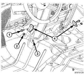
- Remove the nuts (2) and bolts (1) and the center support brackets (4).
 Courtesy of CHRYSLER GROUP, LLC
- Remove the clutch pedal clip and separate the clutch pedal rod, if equipped.
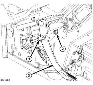
- Remove the brake pedal clip (2) and separate the brake pedal rod (1).
 Courtesy of CHRYSLER GROUP, LLC
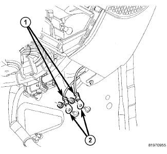
- Remove the nuts and separate the grounds (2).
 Courtesy of CHRYSLER GROUP, LLC
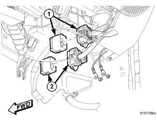
- Disconnect the driver side electrical connectors.
- Disconnect the passenger side electrical connectors (1 and 2).
 Courtesy of CHRYSLER GROUP, LLC
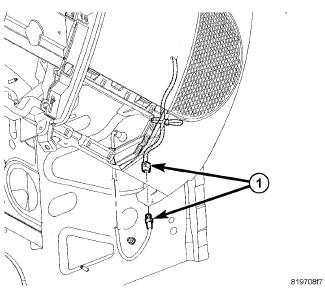
- Disconnect the antenna connector (1).
 Courtesy of CHRYSLER GROUP, LLC
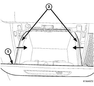
- Remove the glove box (1).
Courtesy of CHRYSLER GROUP, LLC
- Disconnect the positive battery cable.
- Remove the right side ground.
- Position aside the power steering reservoir.
- Remove the battery tray. Refer to TRAY, BATTERY, REMOVAL
.
 Courtesy of CHRYSLER GROUP, LLC
- Drain the refrigerant. Refer to PLUMBING, STANDARD PROCEDURE
.
- Drain the coolant. Refer to STANDARD PROCEDURE
.
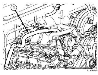
- Remove the EGR tube (1). Refer to VALVE, EXHAUST GAS RECIRCULATION (EGR), 2.8L DIESEL, REMOVAL
.
 Courtesy of CHRYSLER GROUP, LLC
- Remove the upper intake manifold. Refer to MANIFOLD, INTAKE, REMOVAL
or
.
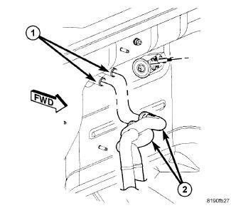
- Using cable-type spring clamp pliers or equivalent, release the hose clamps securing the heater hoses (2) to the heater core tubes (1). Disconnect the hoses from the tubes. Install plugs in, or tape over the opened heater core tubes to prevent coolant spillage during the HVAC housing assembly removal.
 Courtesy of CHRYSLER GROUP, LLC
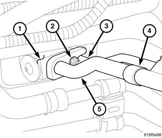
- Remove the nut (2) that securing the A/C liquid line (3) and A/C suction line (5) to the A/C expansion valve (1).
- Disconnect the A/C liquid and suction lines from the A/C expansion valve. Remove and discard the O-ring seals.
- Install plugs in or tape over the opened the refrigerant line fittings and the expansion valve ports.
 Courtesy of CHRYSLER GROUP, LLC
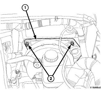
- Position aside the harness at the brake booster.
- Remove the brake booster bracket nuts (2).
 Courtesy of CHRYSLER GROUP, LLC
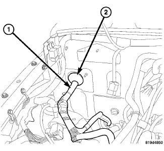
- Release the wire harness grommet (2) and separate any remaining support clips for the wires harness (1).
 Courtesy of CHRYSLER GROUP, LLC
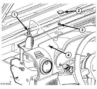
- Remove the trim caps (2) and the fenceline nuts (3).
 Courtesy of CHRYSLER GROUP, LLC
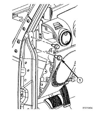
- Remove the side support bolts (1) and position the I/P assembly back.
 Courtesy of CHRYSLER GROUP, LLC
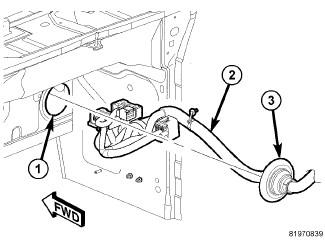
- Pull the main wire harness (2) from the hole in the cowl (1).
 Courtesy of CHRYSLER GROUP, LLC
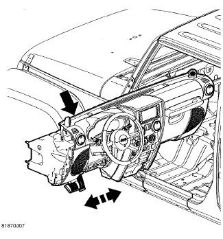
- Remove the I/P from the vehicle.