Part 1 of 2
REMOVAL1. Shift transfer case into NEUTRAL.
2. Raise vehicle.
3. Remove transfer case drain plug and drain transfer case lubricant.
4. Mark front and rear propeller shaft yokes for alignment reference.
5. Support transmission with jack stand.
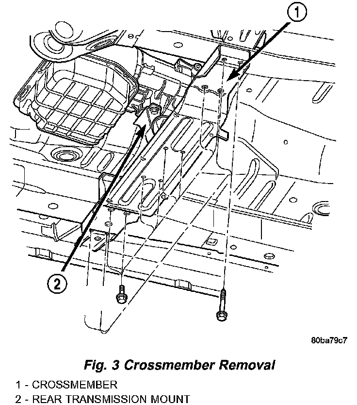
6. Remove rear crossmember and skid plate, if equipped (Fig. 3).
7. Disconnect front/rear propeller shafts at transfer case.
8. Disconnect transfer case cable from range lever.
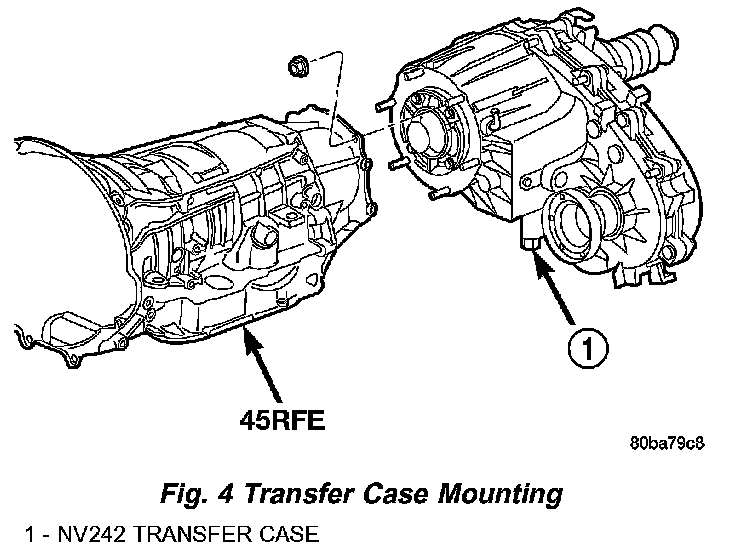
9. Disconnect transfer case vent hose (Fig. 4) and transfer case position sensor.
10. Support transfer case with transmission jack.
11. Secure transfer case to jack with chains.
12. Remove nuts attaching transfer case to transmission.
13. Pull transfer case and jack rearward to disengage transfer case.
14. Remove transfer case from under vehicle.
DISASSEMBLY
REAR RETAINER - NV242LD
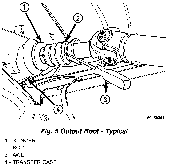
1. Remove output shaft boot. Spread band clamp that secures boot on slinger with a suitable awl. Then slide boot off shaft (Fig. 5).
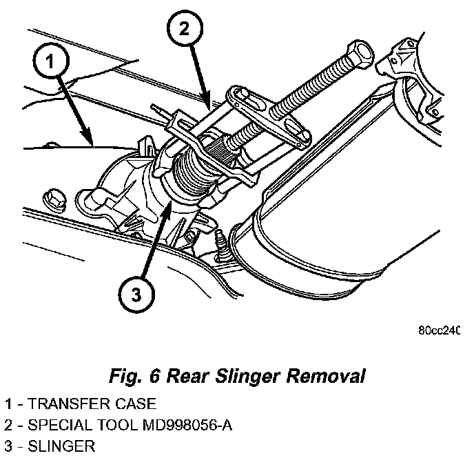
2. Using puller MD-998056-A, remove rear slinger (Fig. 6).
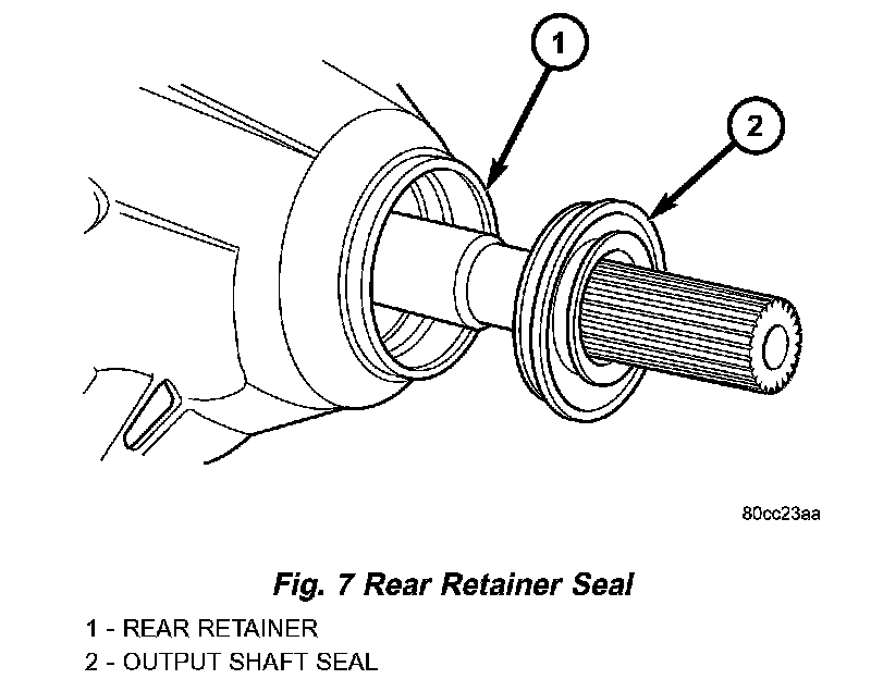
3. Remove rear seal from retainer (Fig. 7). Use pry tool, or collapse seal with punch to remove it.
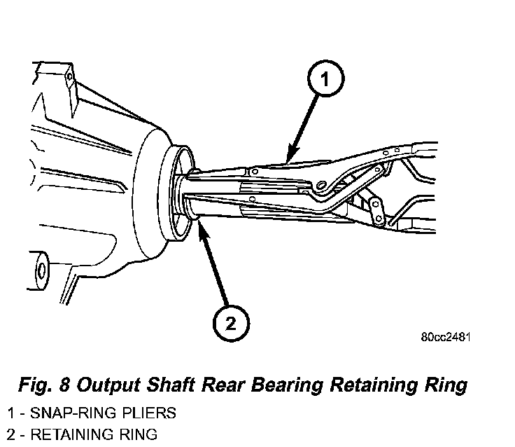
4. Remove rear output bearing I.D. retaining ring (Fig. 8).
5. Remove rear retainer bolts.
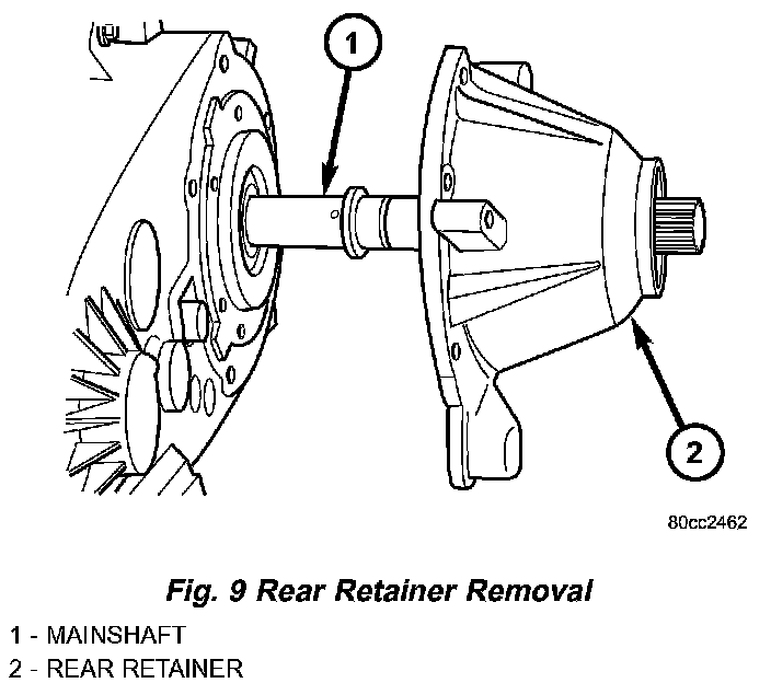
6. Remove rear retainer. Tap retainer with mallet and pry upward to break sealer bead. Then slide retainer off case and output shaft (Fig. 9).
REAR RETAINER - NV242HD
1. Remove extension housing bolts.
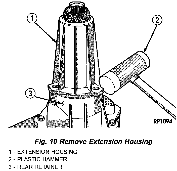
2. Tap extension housing with plastic or rawhide mallet to loosen sealer (Fig. 10).
3. Separate extension housing from rear retainer.
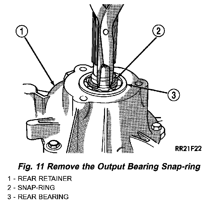
4. Remove rear bearing snap-ring (Fig. 11).
5. Remove bolts holding rear retainer to rear case half.
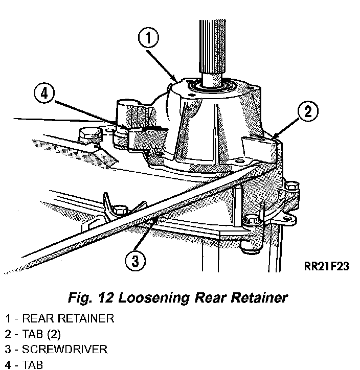
6. Loosen rear retainer with pry tool to break sealer bead. Pry only against retainer boss as shown (Fig. 12).
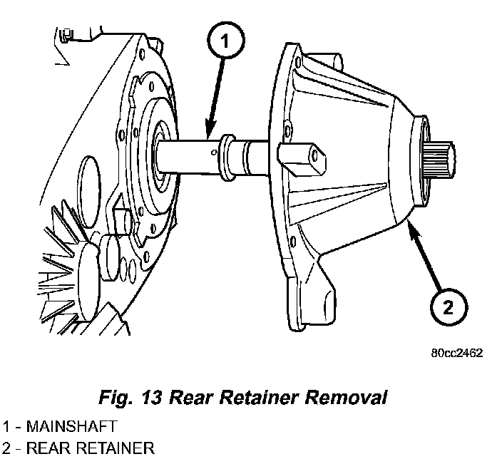
7. Slide retainer off case and output shaft (Fig. 13).
OIL PUMP AND REAR CASE HALF
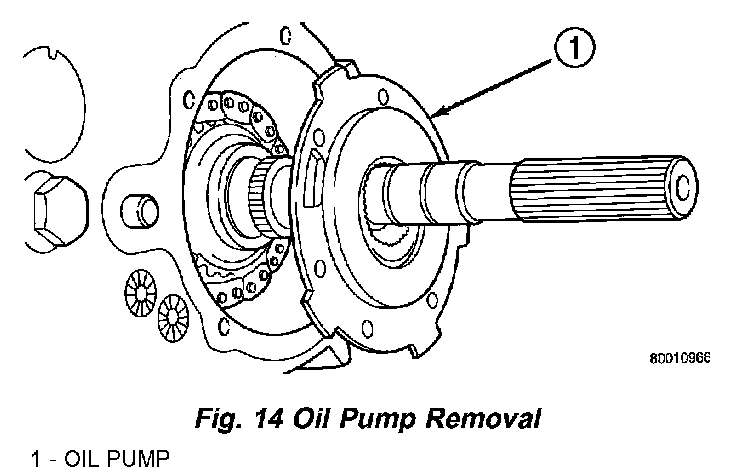
1. Remove rear bearing O.D. retaining ring with snap ring pliers. Then tilt pump and slide it off output shaft (Fig. 14)
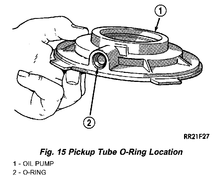
2. Remove pickup tube O-ring from pump (Fig. 15) but do not disassemble pump; it is not a repairable part.
3. Remove seal from oil pump with pry tool.
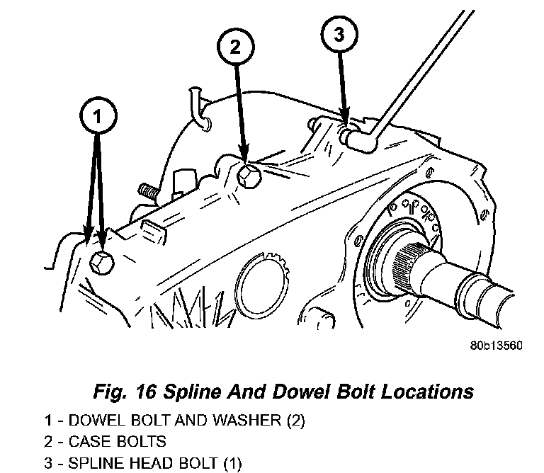
4. Remove bolts attaching rear case to front case (Fig. 16). Note position of the two black finish bolts at each end of the case. These bolts go through the case dowels and require a washer under the bolt head.
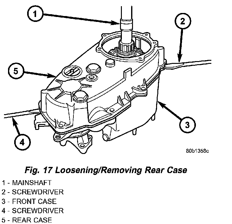
5. Remove rear case from front case (Fig. 17). Insert screwdrivers into slots cast into each end of case. Then pry upward to break sealer bead and remove rear case.
CAUTION: Do not pry on the sealing surface of either case half as the surfaces will become damaged.
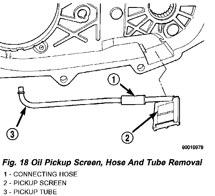
6. Remove oil pickup tube and screen from rear case (Fig. 18).
COMPANION FLANGE AND RANGE LEVER
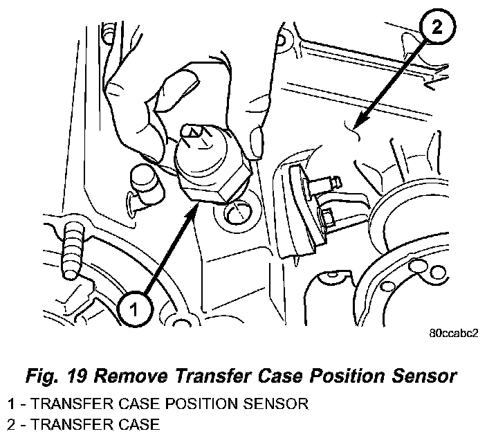
1. Remove transfer case position sensor (Fig. 19).
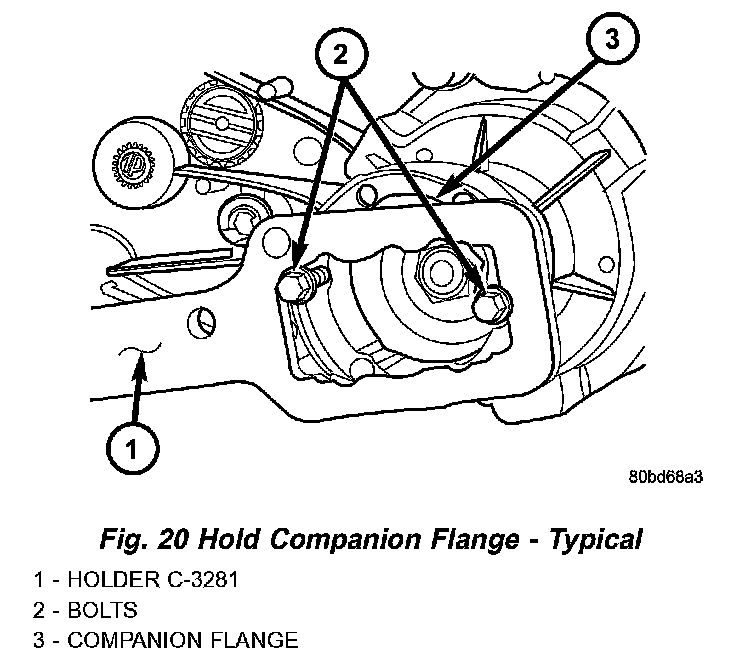
2. Install two bolts (Fig. 20) partially into the propeller shaft companion flange, 180° from each other.
3. Install the rectangular end of the Flange Holder C-3281 over the bolts to hold the companion flange stationary and remove the nut holding the companion flange to the output shaft.
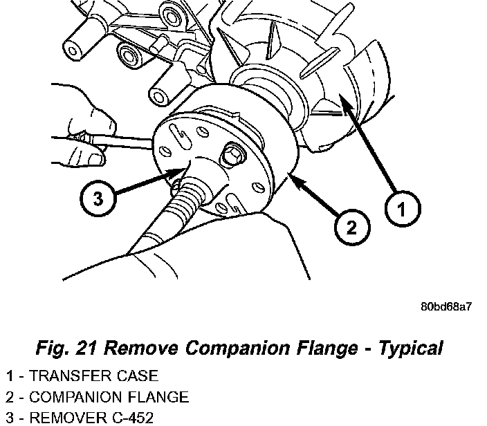
4. Use Remover C-452 (Fig. 21) to remove the companion flange.
5. Remove seal washer from front output shaft. Discard washer as it should not be reused.
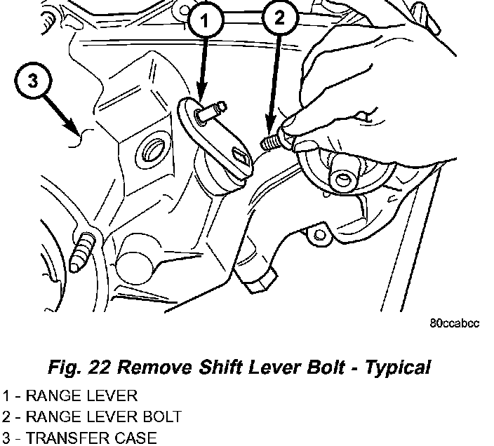
6. Remove the bolt (Fig. 22) that attaches the range lever to sector shaft. Then move sector to neutral position and remove range lever from shaft.
NOTE: Be sure to note the orientation of the range lever (lever up or down) so that it may be re-installed in the same direction.
FRONT OUTPUT SHAFT AND DRIVE CHAIN
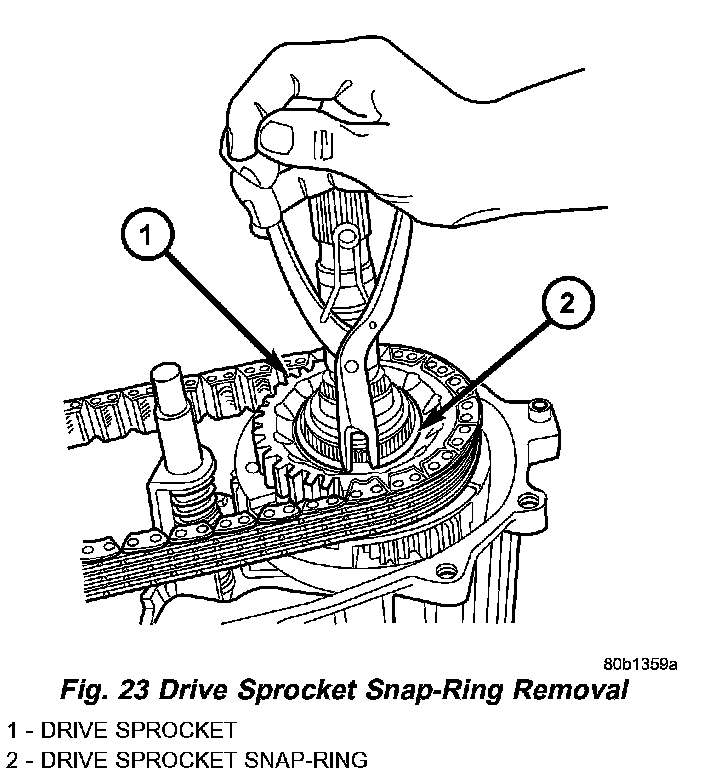
1. Remove drive sprocket snap-ring (Fig. 23).
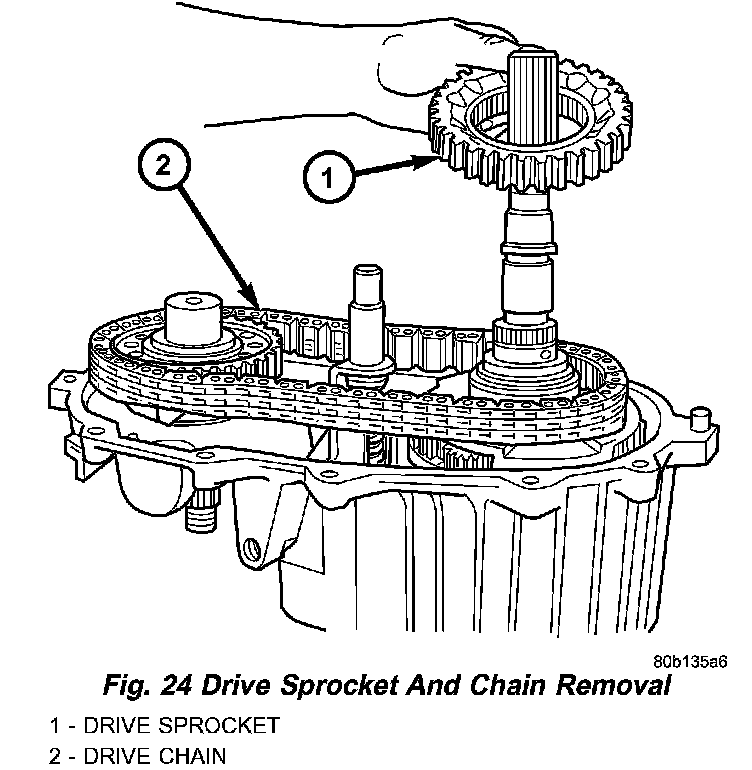
2. Remove drive sprocket and chain (Fig. 24).
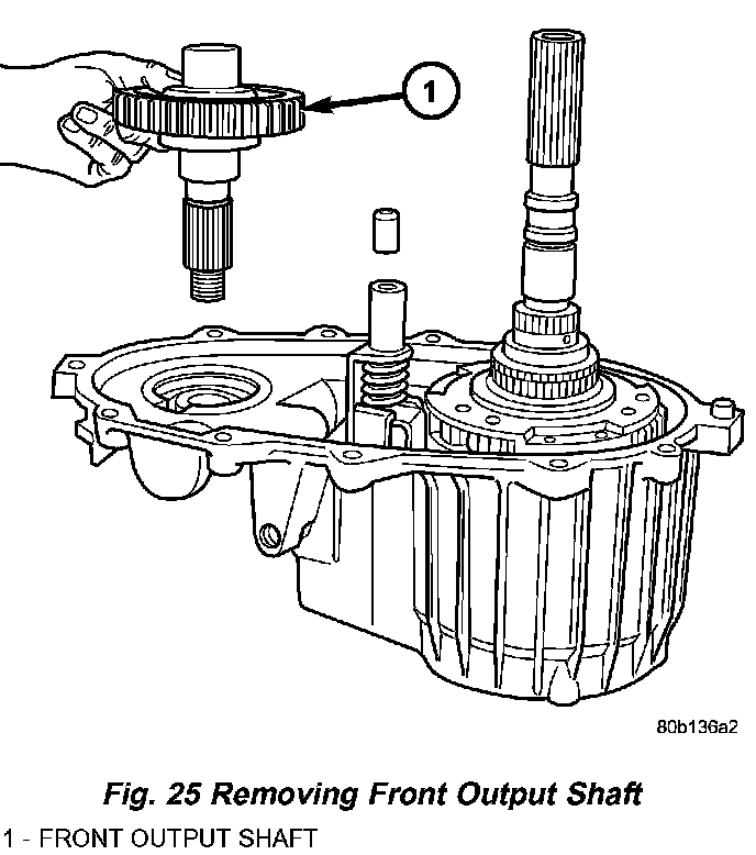
3. Remove front output shaft (Fig. 25).
SHIFT FORKS AND MAINSHAFT
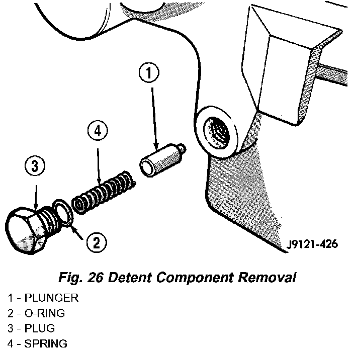
1. Remove shift detent plug, spring and pin (Fig. 26).
2. Remove seal plug from low range fork lockpin access hole. Then move shift sector to align low range fork lockpin with access hole.
3. Remove range fork lockpin with size number one easy-out tool as follows:
a. Insert easy-out tool through access hole inside of transfer case and into lock-pin.
b. Tap easy-out tool into lock-pin with hammer until tool is securely engaged into the lock-pin.
c. Install a t-handle, such as from a tap and die set, onto the easy-out tool.
d. Securely tighten the t-handle onto the tool.
e. In one motion, pull upward and turn the t-handle counter-clockwise to remove the lock-pin.
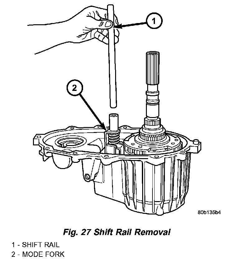
4. Remove shift rail by pulling it straight up and out of fork (Fig. 27).
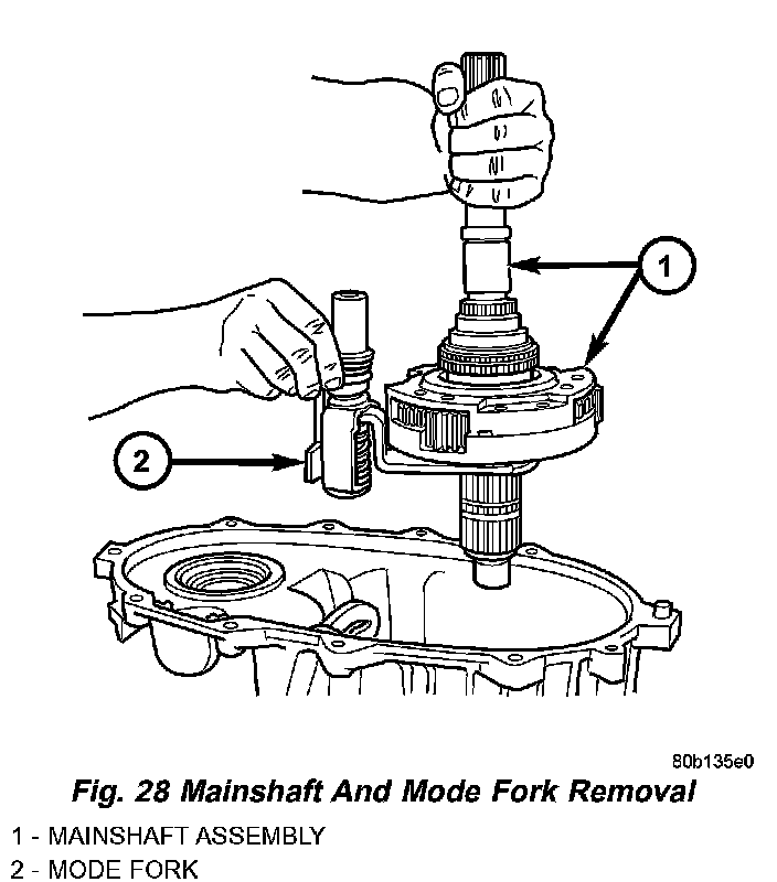
5. Remove mode fork and mainshaft as assembly (Fig. 28).
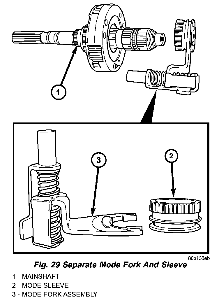
6. Remove mode shift sleeve and mode fork assembly from mainshaft (Fig. 29). Note position of mode sleeve in fork and remove sleeve.
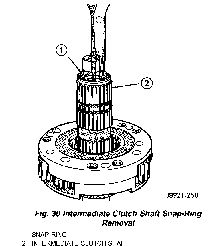
7. Remove intermediate clutch shaft snap-ring (Fig. 30).
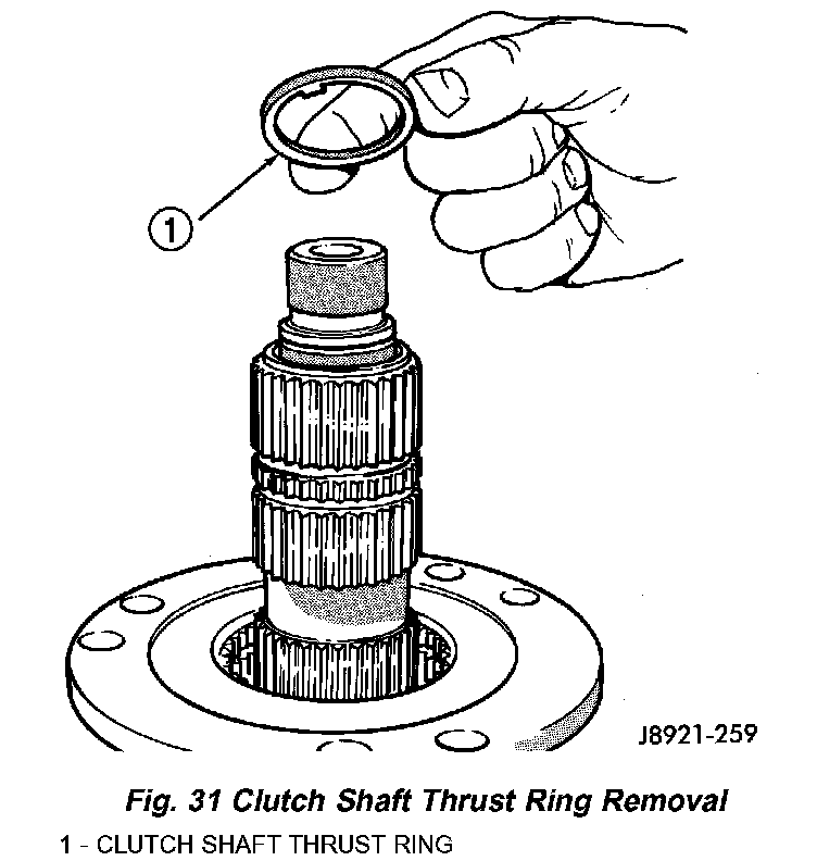
8. Remove clutch shaft thrust ring (Fig. 31).
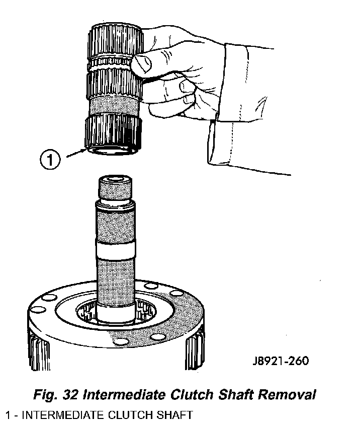
9. Remove intermediate clutch shaft (Fig. 32).
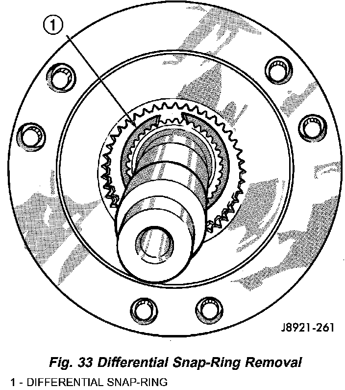
10. Remove differential snap-ring (Fig. 33).
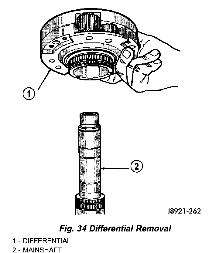
11. Remove differential (Fig. 34).
12. Remove differential needle bearings and both needle bearing thrust washers from mainshaft.
13. Slide low range fork pin out of shift sector slot.
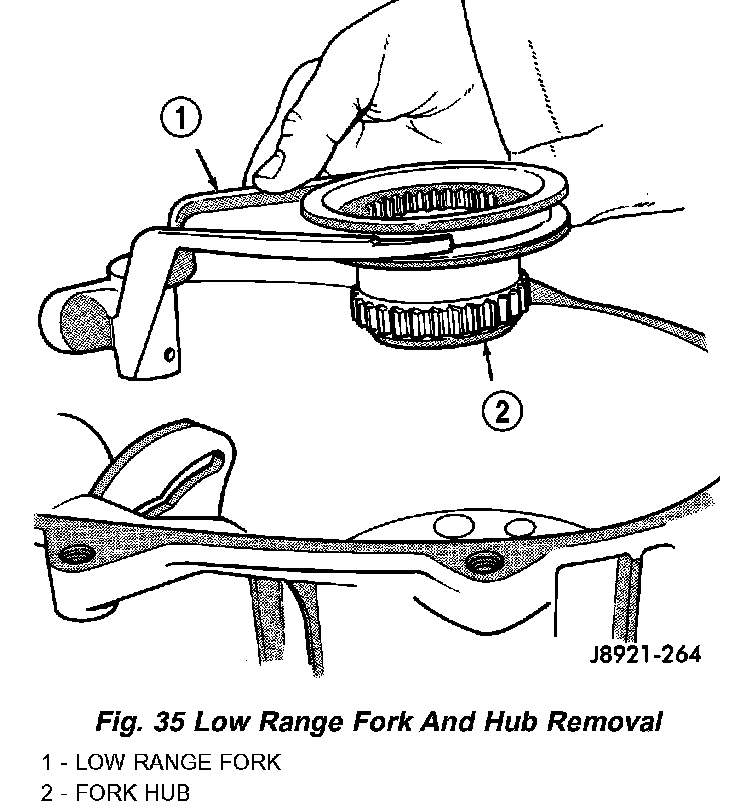
14. Remove low range fork and sleeve (Fig. 35).
15. Remove shift sector.
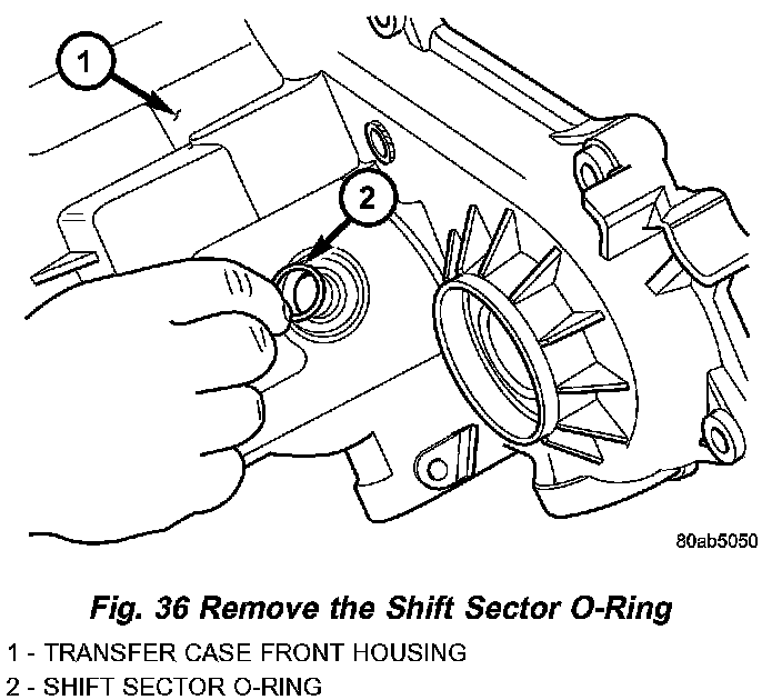
16. Remove the shift sector shaft bushing and O-ring (Fig. 36).
INPUT GEAR/LOW RANGE ASSEMBLY
1. Remove front bearing retainer bolts.

2. Remove front bearing retainer. Carefully pry retainer loose with screwdriver (Fig. 37). Position screwdriver in slots cast into retainer.
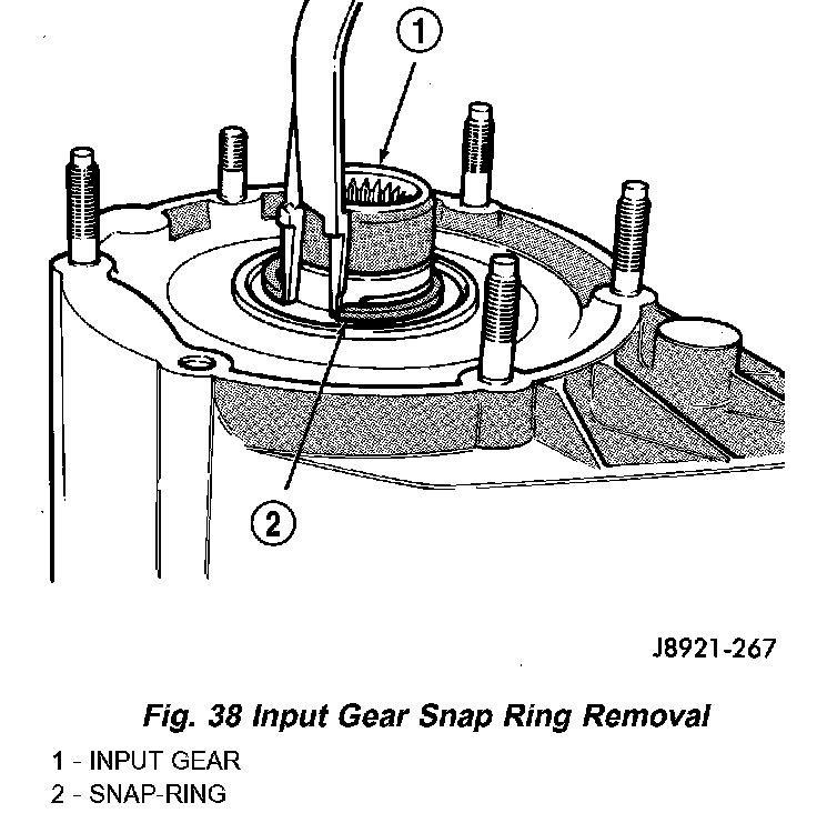
3. Remove input gear snap-ring (Fig. 38).
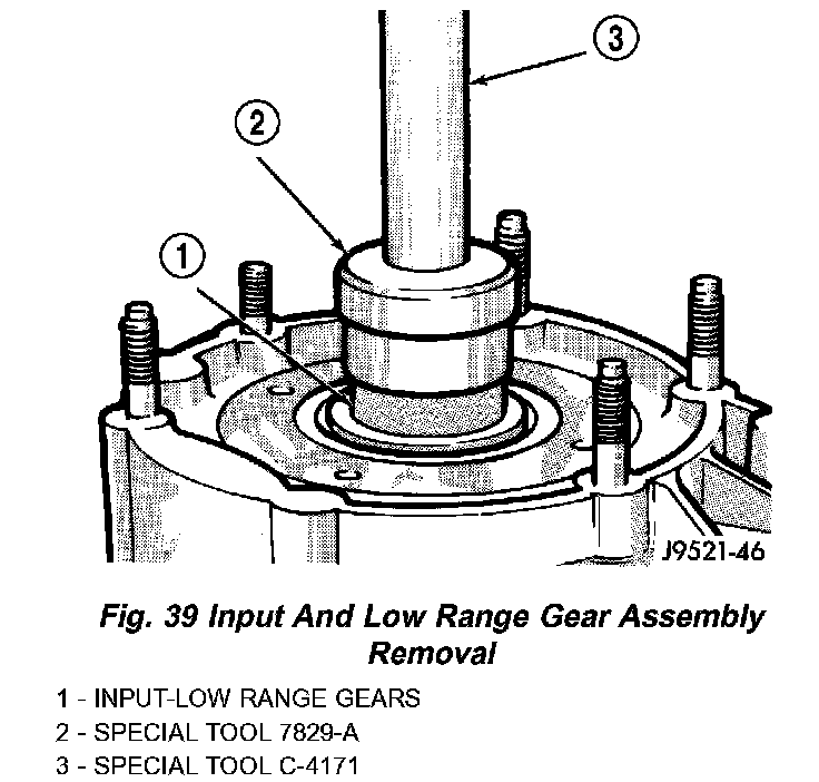
4. Remove input/low range gear assembly from bearing with Tool Handle C-4171 and Tool 7829A (Fig. 39).
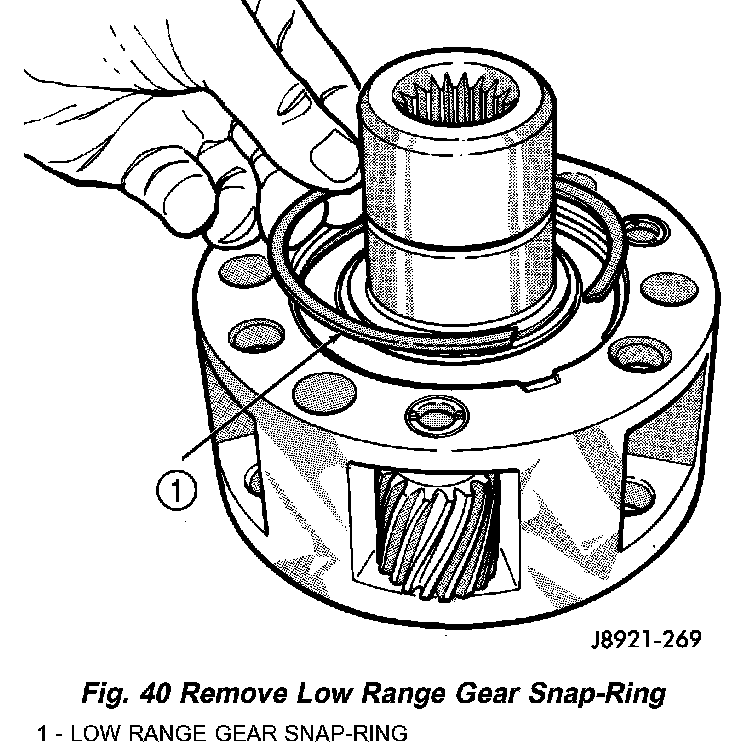
5. Remove low range gear snap-ring (Fig. 40).
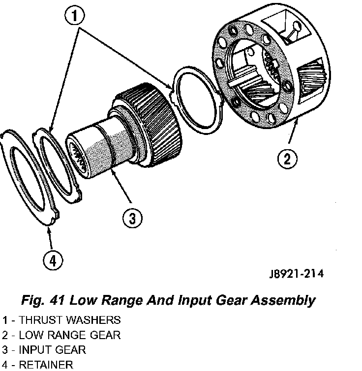
6. Remove input gear retainer, thrust washers and input gear from low range gear (Fig. 41).
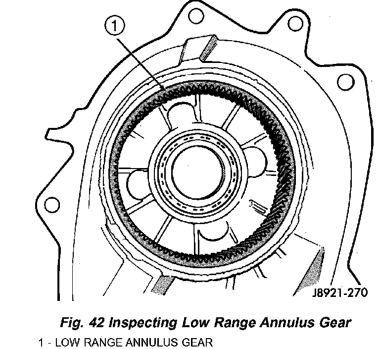
7. Inspect low range annulus gear (Fig. 42). Gear is not a serviceable component. If damaged, replace gear and front case as assembly.
8. Remove oil seals from following components:
- front bearing retainer.
- rear retainer.
- oil pump.
- case halves.
DIFFERENTIAL
1. Mark differential case halves for reference.
2. Remove differential case bolts.
3. Invert differential on workbench.
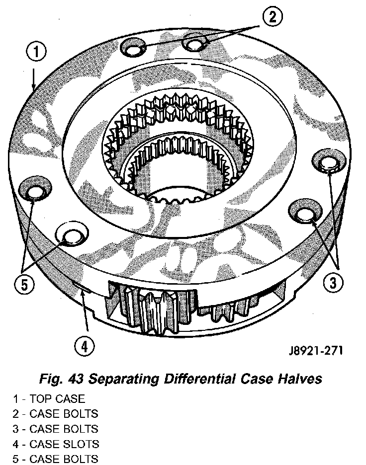
4. Separate top case from bottom case. Use slots in case halves to pry them apart (Fig. 43).
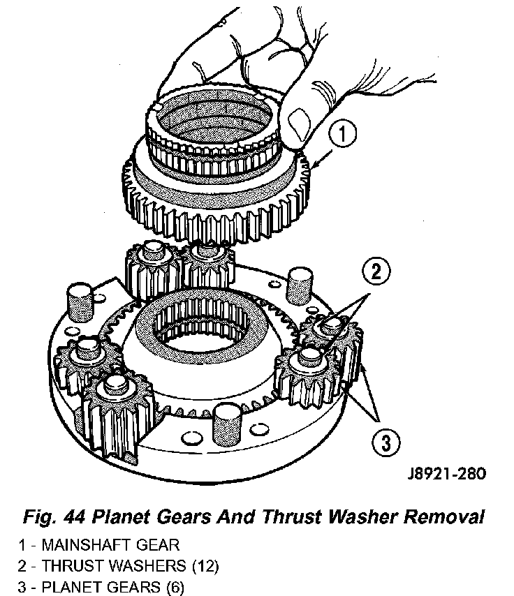
5. Remove thrust washers and planet gears from case pins (Fig. 44).
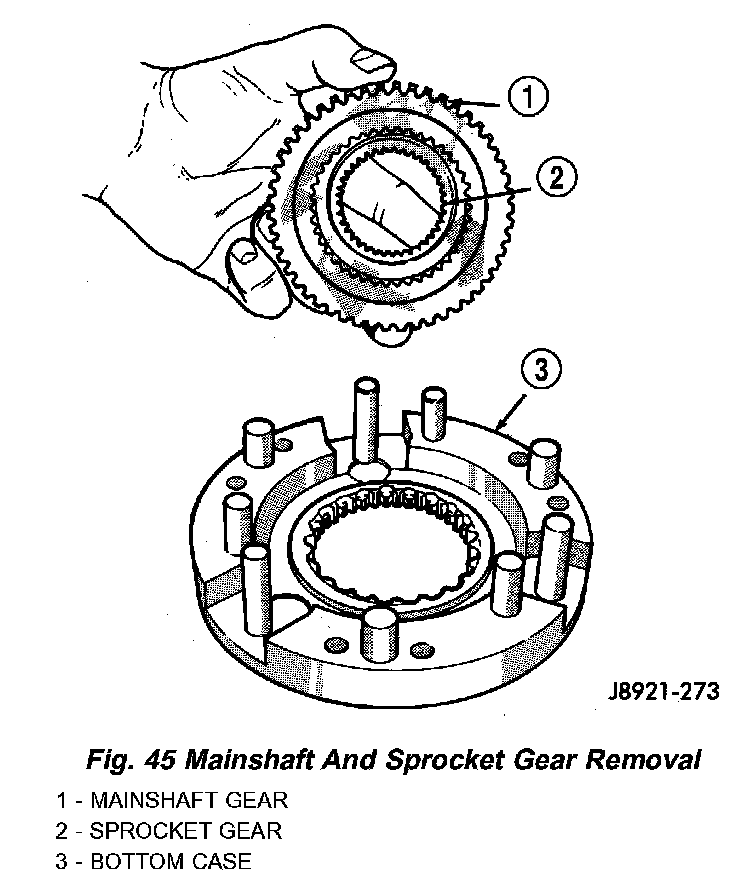
6. Remove mainshaft and sprocket gears from bottom case (Fig. 45). Note gear position for reference before separating them.
CLEANING
Clean the transfer case parts with a standard parts cleaning solvent. Remove all traces of sealer from the cases and retainers with a scraper and all purpose cleaner. Use compressed air to remove solvent residue from oil feed passages in the case halves, retainers, gears, and shafts.
The oil pickup screen can be cleaned with solvent. Shake excess solvent from the screen after cleaning and allow it to air dry. Do not use compressed air.
INSPECTION
MAINSHAFT/SPROCKET/HUB
Inspect the splines on the hub and shaft and the teeth on the sprocket. Minor nicks and scratches can be smoothed with an oilstone. However, replace any part that is damaged.
Check the contact surfaces in the sprocket bore and on the mainshaft. Minor nicks and scratches can be smoothed with 320-400 grit emery cloth but do not try to salvage the shaft if nicks or wear is severe.
INPUT GEAR AND PLANETARY CARRIER
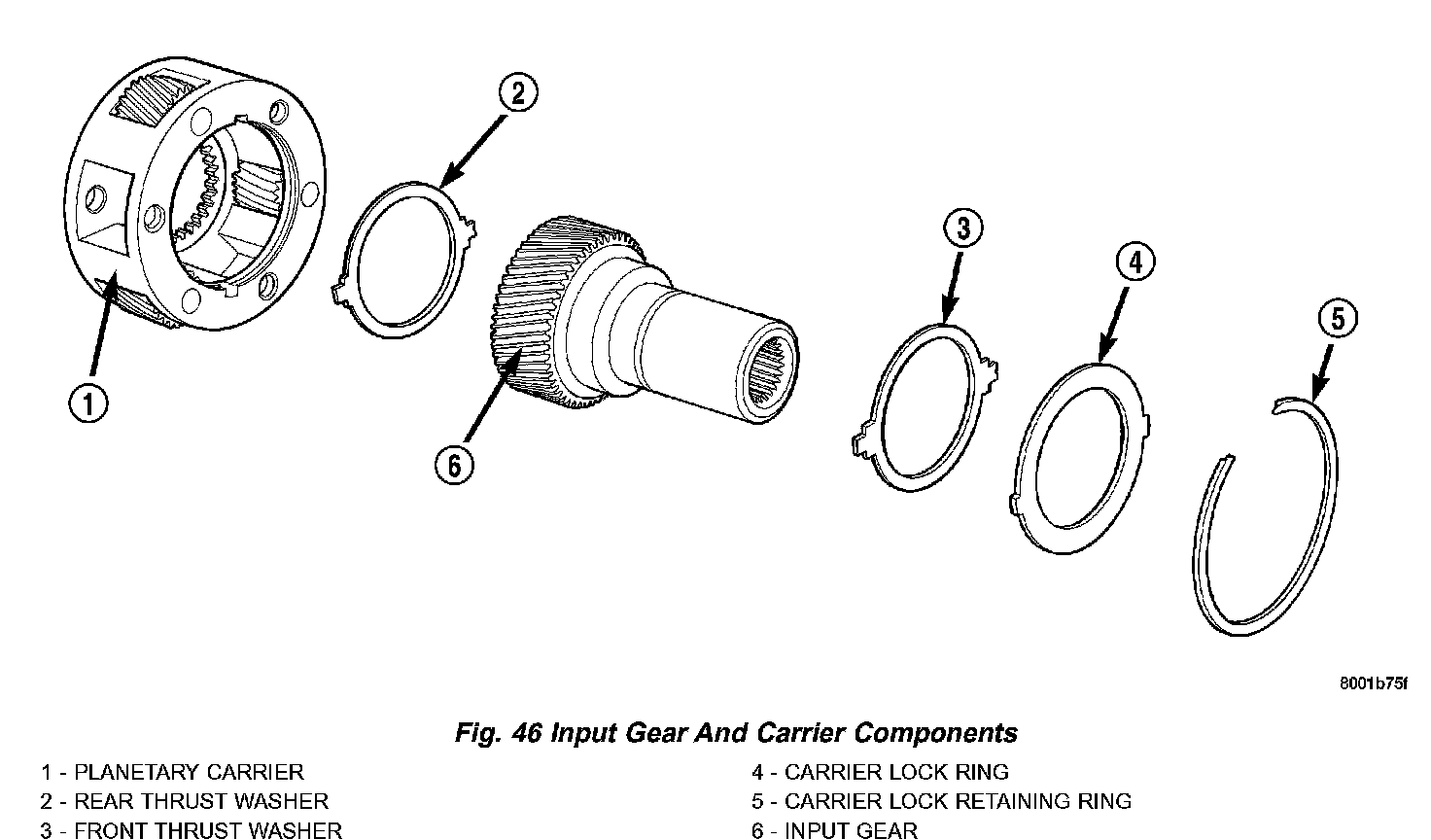
Check the teeth on the gear (Fig. 46). Minor nicks can be dressed off with an oilstone but replace the gear if any teeth are broken, cracked, or chipped. The bearing surface on the gear can be smoothed with 300-400 grit emery cloth if necessary.
Examine the carrier body and pinion gears for wear or damage. The carrier will have to be replaced as an assembly if the body, pinion pins, or pinion gears are damaged.
Check the lock ring and both thrust washers for wear or cracks. Replace them if necessary. Also replace the lock retaining ring if bent, distorted, or broken.