Vacuum Control System Diagnosis
Vacuum control is used to operate the mode doors in the standard equipment manual temperature control system HVAC housing. Testing of the A/C Heater mode control switch operation will determine if the vacuum and electrical controls are functioning. However, it is possible that a vacuum control system that operates perfectly at engine idle (high engine vacuum) may not function properly at high engine speeds or loads (low engine vacuum). This can be caused by leaks in the vacuum system, or a faulty vacuum check valve.A vacuum system test will help to identify the source of poor vacuum system performance or vacuum system leaks. Before starting this test, stop the engine and make certain that the problem isn't a disconnected vacuum supply tube at the engine intake manifold vacuum tap or the vacuum reservoir.
Fig.1 Adjust Vacuum Test Bleed Valve - Typical:
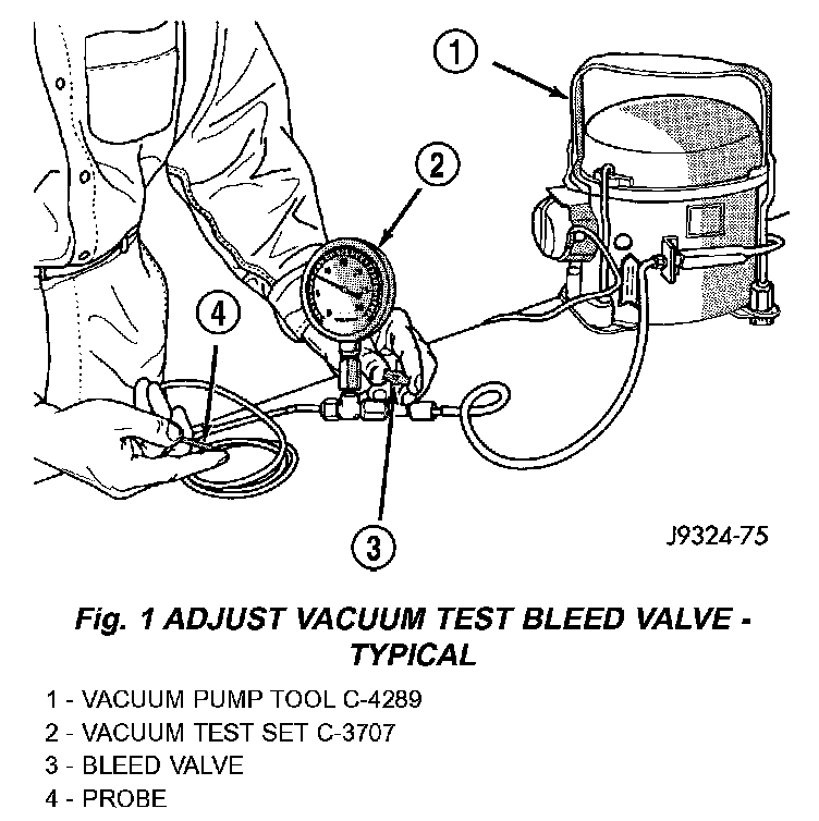
Use an adjustable vacuum test set (Special Tool C-3707-B) and a suitable vacuum pump to test the HVAC vacuum control system. With a finger placed over the end of the vacuum test hose probe, adjust the bleed valve on the test set gauge to obtain a vacuum of exactly 27 kPa (8 in. Hg.). Release and block the end of the probe several times to verify that the vacuum reading returns to the exact 27 kPa (8 in. Hg.) setting. Otherwise, a false reading will be obtained during testing.
Vacuum Check Valves
1. Remove the vacuum check valve to be tested. The valves are located in the (black) vacuum supply tubes at either the engine intake manifold vacuum tap, or on the bottom of the HVAC unit behind the passenger front floor duct.
2. Connect the test set vacuum supply hose to the A/C Heater control side of the valve. When connected to this side of the check valve, no vacuum should pass and the test set gauge should return to the 27 kPa (8 in. Hg.) setting. If OK, go to Step 3. If not OK, replace the faulty valve.
3. Connect the test set vacuum supply hose to the engine vacuum side of the valve. When connected to this side of the check valve, vacuum should flow through the valve without restriction. If not OK, replace the faulty valve.
A/C Heater Control
1. Connect the test set vacuum probe to the HVAC vacuum supply (black) tube in the engine compartment. Position the test set gauge so that it can be viewed from the passenger compartment.
2. Place the A/C Heater mode control switch knob in each mode position, one position at a time, and pause after each selection. The test set gauge should return to the 27 kPa (8 in. Hg.) setting shortly after each selection is made. If not OK, a component or vacuum line in the vacuum circuit of the selected mode has a leak. See the procedure in Locating Vacuum Leaks.
CAUTION: Do not use lubricant on the switch ports or in the holes in the plug, as lubricant will ruin the vacuum valve in the switch. A drop of clean water in the connector plug holes will help the connector slide onto the switch ports.
Locating Vacuum Leaks
WARNING: ON VEHICLES EQUIPPED WITH AIRBAGS, DISABLE THE AIRBAG SYSTEM BEFORE ATTEMPTING ANY STEERING WHEEL, STEERING COLUMN, OR INSTRUMENT PANEL COMPONENT DIAGNOSIS OR SERVICE. DISCONNECT AND ISOLATE THE BATTERY NEGATIVE (GROUND) CABLE, THEN WAIT TWO MINUTES FOR THE AIRBAG SYSTEM CAPACITOR TO DISCHARGE BEFORE PERFORMING FURTHER DIAGNOSIS OR SERVICE. THIS IS THE ONLY SURE WAY TO DISABLE THE AIRBAG SYSTEM. FAILURE TO TAKE THE PROPER PRECAUTIONS COULD RESULT IN AN ACCIDENTAL AIRBAG DEPLOYMENT AND POSSIBLE PERSONAL INJURY.
1. Disconnect the vacuum harness connector from the back of the A/C Heater mode control switch on the control panel.
Fig.2 Vacuum Circuit Test:
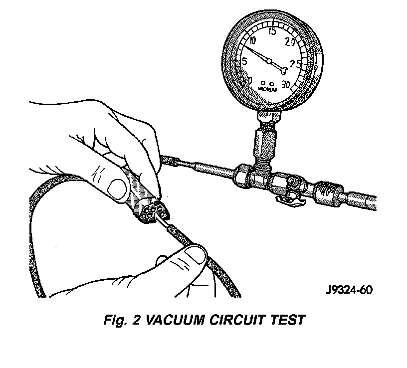
2. Connect the test set vacuum hose probe to each port in the vacuum harness connector, one at a time, and pause after each connection. The test set gauge should return to the 27 kPa (8 in. Hg.) setting shortly after each connection is made. If OK, replace the faulty mode control switch. If not OK, go to Step 3.
Fig.3 Vacuum Circuits:
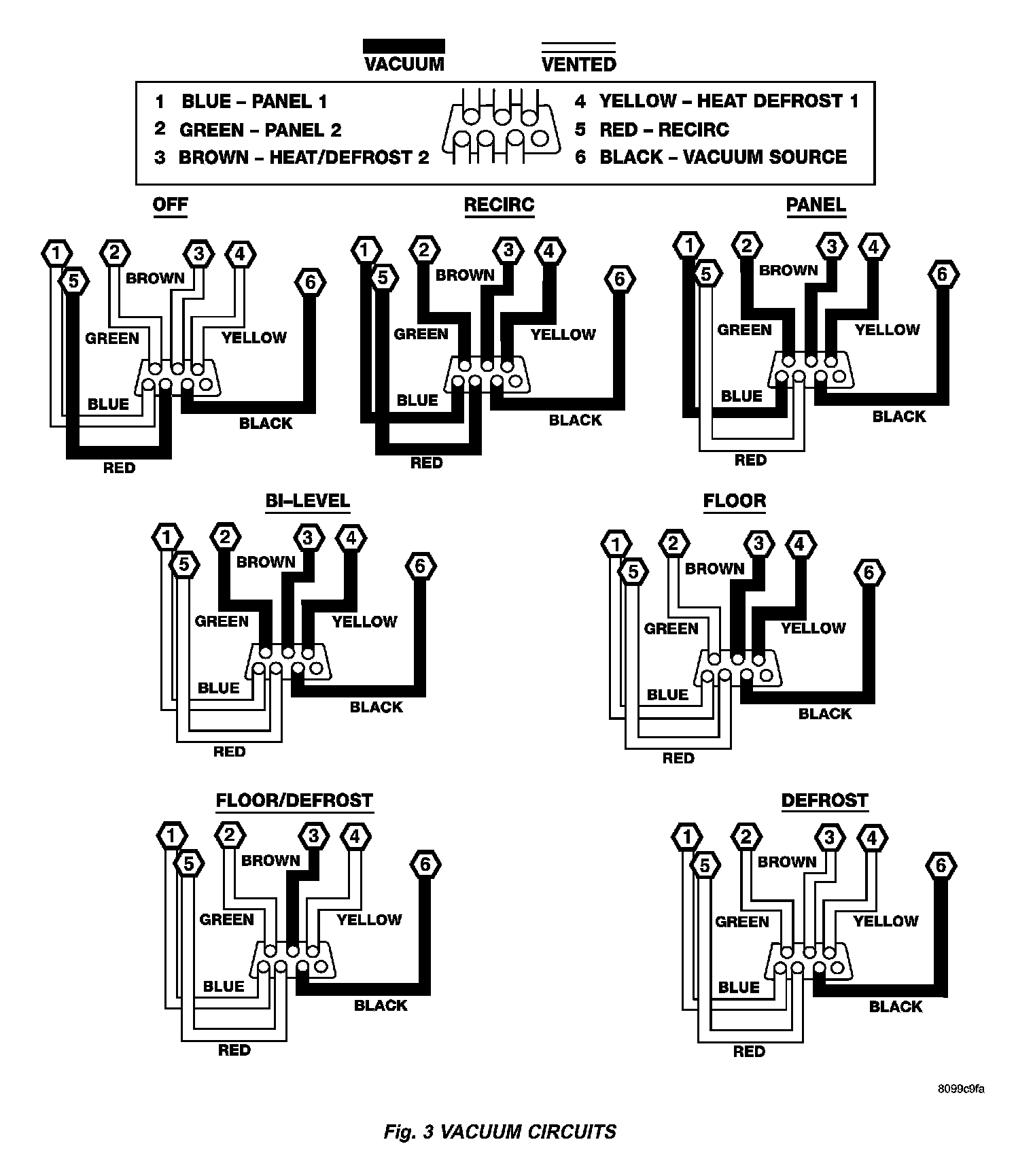
3. Determine the vacuum line color of the vacuum circuit that is leaking. To determine the vacuum line colors, refer to the Vacuum Circuits chart.
4. Disconnect and plug the vacuum line from the component (fitting, actuator, valve, switch, or reservoir) on the other end of the leaking circuit. Instrument panel disassembly or removal may be necessary to gain access to some components.
5. Connect the test set hose or probe to the open end of the leaking circuit. The test set gauge should return to the 27 kPa (8 in. Hg.) setting shortly after each connection is made. If OK, replace the faulty disconnected component. If not OK, go to Step 6.
6. To locate a leak in a vacuum line, leave one end of the line plugged and connect the test set hose or probe to the other end. Run your fingers slowly along the line while watching the test set gauge. The vacuum reading will fluctuate when your fingers contact the source of the leak. To repair the vacuum line, cut out the leaking section of the line. Then, insert the loose ends of the line into a suitable length of 3 millimeter (1/8-inch) inside diameter rubber hose.