Front Wiper & Washer System
DIAGNOSIS AND TESTING - FRONT WIPER & WASHER SYSTEMWIPER SYSTEM
If the front wiper motor operates, but the wipers do not move on the windshield, replace the faulty front wiper module. If the wipers operate, but chatter, lift, or do not clear the glass, clean and inspect the wiper system components as required. Refer to the appropriate wiring information. The wiring information includes wiring diagrams, proper wire and connector repair procedures, details of wire harness routing and retention, connector pin-out information and location views for the various wire harness connectors, splices and grounds.
The hard wired circuits and components of the front wiper and washer system may be diagnosed and tested using conventional diagnostic tools and procedures. However, conventional diagnostic methods may not prove conclusive in the diagnosis of the Body Control Module (BCM), the Rain Sensor Module (RSM), the Powertrain Control Module (PCM), or the inputs to or outputs from these modules that control the various front wiper and washer system operating modes. The most reliable, efficient, and accurate means to diagnose the BCM, the RSM, the PCM or the BCM inputs and outputs related to the various front wiper and washer system operating modes requires the use of a DRBIII scan tool. Refer to the appropriate diagnostic information.
WARNING: ON VEHICLES EQUIPPED WITH AIRBAGS, DISABLE THE SUPPLEMENTAL RESTRAINT SYSTEM BEFORE ATTEMPTING ANY STEERING WHEEL, STEERING COLUMN, DRIVER AIRBAG, PASSENGER AIRBAG, SIDE CURTAIN AIRBAG, FRONT IMPACT SENSOR, SIDE IMPACT SENSOR, OR INSTRUMENT PANEL COMPONENT DIAGNOSIS OR SERVICE. DISCONNECT AND ISOLATE THE BATTERY NEGATIVE (GROUND) CABLE, THEN WAIT TWO MINUTES FOR THE SYSTEM CAPACITOR TO DISCHARGE BEFORE PERFORMING FURTHER DIAGNOSIS OR SERVICE. THIS IS THE ONLY SURE WAY TO DISABLE THE SUPPLEMENTAL RESTRAINT SYSTEM. FAILURE TO TAKE THE PROPER PRECAUTIONS COULD RESULT IN ACCIDENTAL AIRBAG DEPLOYMENT AND POSSIBLE PERSONAL INJURY.
AUTOMATIC WIPER ONLY - FALSE WIPES
False wipes are unnecessary wipes that occur when the control knob of the right multi-function switch is in one of the five Auto sensitivity positions and no rain or moisture is apparent within the wipe pattern on the windshield glass. Because this system is designed to operate whenever it detects moisture, if the switch is in one of the Auto sensitivity positions any road spray bug splatters, or mist from passing cars or trucks may occasionally cause the wipers to cycle. Also, the system will perform an initialization wipe each time the ignition switch is turned to the On position while one of the Auto positions is still selected. These are normal characteristics of this system and are not false wipes.
False wipes generally are the result of foreign material or flaws that interfere with the system optics. The optics for this system allow the Rain Sensor Module (RSM) to precisely transmit several InfraRed (IR) light beams and precisely monitor the intensity of these beams on the outer surface of the windshield glass to determine the presence of moisture. The sensitivity of this system is such that anything that distorts the focus or intensity of the IR light beams or affects the ability of the photo diodes within the RSM to see and accurately measure these light beams can result in the RSM logic misinterpreting the resulting input data as moisture on the windshield. The optics for this system include the lenses of the RSM, the lenses of the RSM bracket, the adhesive layer that bonds the RSM bracket to the inside of the windshield, and the windshield glass.
The following procedure should only be used if false wipe occurrences are frequent and persistent. Perform diagnosis of the front wiper system, the right multi-function switch, and the RSM using a DRBIII scan tool and the appropriate diagnostic procedures before performing the following:
Fig. 2 Rain Sensor Module:
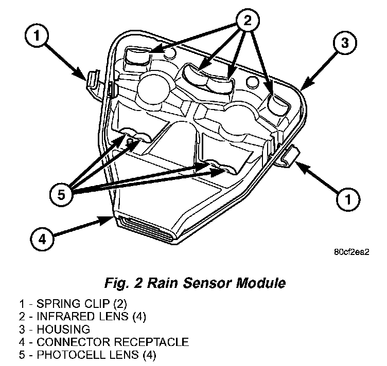
1. Remove the RSM trim cover. Confirm that the spring clips of the RSM are fully engaged in their slots on each outboard edge of the RSM bracket on the inside of the windshield glass. If OK, go to Step 2. If not OK, press the spring clips inward until they snap over the bracket and are fully engaged in their slots.
Fig. 3 RSM Bracket Inspection:
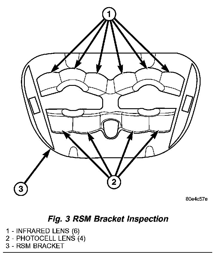
2. Remove the RSM from the RSM bracket. Inspect the RSM lenses and the RSM bracket lenses for contamination. If OK, go to Step 3. If not OK, clean any foreign material from each of these lenses using rubbing alcohol and a lint-free cloth.
3. Carefully inspect the RSM for any physical damage, including scratches on the RSM lenses. If OK, go to Step 4. If not OK, replace the damaged RSM.
NOTE: The Rain Sensor Module (RSM) bracket is serviced as a unit with the windshield glass. If either the bracket or the glass is faulty or damaged, the entire RSM bracket and windshield glass unit must be replaced.
4. Carefully inspect the RSM bracket for any physical damage, including scratches on the RSM bracket lenses. If OK. go to Step 5. If not OK, replace the damaged RSM bracket and windshield as a unit.
5. Carefully inspect the outer surface of the windshield glass for physical damage, including scratches, cracks or chips in the vicinity of the RSM bracket lenses. Scratches, cracks or chips in the windshield glass outside the area of the RSM bracket lenses will not cause false wipes. If OK, go to Step 6. If not OK, replace the damaged windshield.
6. From the outside of the windshield glass, carefully inspect the adhesive layer between the windshield glass and the RSM bracket for any large voids. If an adhesive void greater than about 8 millimeters (0.31 inch) is observed, replace the faulty RSM bracket and windshield unit.
WASHER SYSTEM
The diagnosis found here addresses an electrically inoperative front washer system. If the front washer pump/motor operates, but no washer fluid is emitted from the front washer nozzles, be certain to check the fluid level in the reservoir. Also clean and inspect the front washer system components as required. Refer to the appropriate wiring information. The wiring information includes wiring diagrams, proper wire and connector repair procedures, details of wire harness routing and retention, connector pin-out information and location views for the various wire harness connectors, splices and grounds.
WARNING: ON VEHICLES EQUIPPED WITH AIRBAGS, DISABLE THE SUPPLEMENTAL RESTRAINT SYSTEM BEFORE ATTEMPTING ANY STEERING WHEEL, STEERING COLUMN, DRIVER AIRBAG, PASSENGER AIRBAG, SIDE CURTAIN AIRBAG, FRONT IMPACT SENSOR, SIDE IMPACT SENSOR, OR INSTRUMENT PANEL COMPONENT DIAGNOSIS OR SERVICE. DISCONNECT AND ISOLATE THE BATTERY NEGATIVE (GROUND) CABLE, THEN WAIT TWO MINUTES FOR THE SYSTEM CAPACITOR TO DISCHARGE BEFORE PERFORMING FURTHER DIAGNOSIS OR SERVICE. THIS IS THE ONLY SURE WAY TO DISABLE THE SUPPLEMENTAL RESTRAINT SYSTEM. FAILURE TO TAKE THE PROPER PRECAUTIONS COULD RESULT IN ACCIDENTAL AIRBAG DEPLOYMENT AND POSSIBLE PERSONAL INJURY.
1. Turn the ignition switch to the On position. Turn the control knob on the control stalk of the right (wiper) multi-function switch to the Low or High wiper position. Check whether the front wiper system is operating. If OK, go to Step 2. If not OK, test and repair the front wiper system before continuing with these tests. Refer to WIPER SYSTEM.
2. Turn the control knob on the control stalk of the right (wiper) multi-function switch to the Off position. Pull the control stalk of the right (wiper) multi-function switch toward the steering wheel to close the front washer switch. The front washer pump should operate and the front wipers should operate for about three sweep cycles after the switch is released before they park. If the front wipers are OK, but the front washers are not, go to Step 3. If the front washers are OK, but the front wipers are not, go to Step 5.
3. Turn the ignition switch to the Off position. Disconnect and isolate the battery negative cable. Disconnect the left headlamp and dash wire harness connector for the front washer pump/motor from the pump/motor connector receptacle. Check for continuity between the ground circuit cavity of the left headlamp and dash wire harness connector for the front washer pump/motor and a good ground. There should be continuity If OK, go to Step 4. If not OK, repair the open ground circuit to ground (G106) as required.
4. Reconnect the battery negative cable. Turn the ignition switch to the On position. While pulling the control stalk of the right (wiper) multi-function switch toward the steering wheel to close the front washer switch, check for battery voltage at the washer pump switch sense circuit cavity of the left headlamp and dash wire harness connector for the front washer pump/motor unit. If OK, replace the faulty front washer pump/motor. If not OK, repair the open washer pump switch sense circuit between the right (wiper) multi-function switch and the front washer pump/motor unit as required.
5. Turn the ignition switch to the Off position. Disconnect and isolate the battery negative cable. Disconnect the instrument panel wire harness connector (Connector C2) for the Body Control Module (BCM) from the BCM connector receptacle. Reconnect the battery negative cable. Turn the ignition switch to the On position. While pulling the control stalk of the right (wiper) multi-function switch toward the steering wheel to close the front washer switch, check for battery voltage at the washer pump switch sense circuit cavity of the instrument panel wire harness connector (Connector C2) for the BCM. If OK, use a DRBIII scan tool to diagnose the BCM. Refer to the appropriate diagnostic information. If not OK, repair the open washer pump switch sense circuit between the right (wiper) multi-function switch and the BCM as required.