Rear Axle - 198RBI
PINION GEAR/RING GEARREMOVAL
NOTE: The ring and pinion gears are serviced as a matched set. Never replace one gear without the other gear.
1. Raise and support vehicle.
2. Mark pinion yoke and propeller shaft for installation reference.
3. Disconnect propeller shaft from pinion yoke and tie shaft to underbody
4. Remove differential from the housing.
5. Place differential case in a vise with soft metal jaw.
6. Remove bolts holding ring gear to differential case.
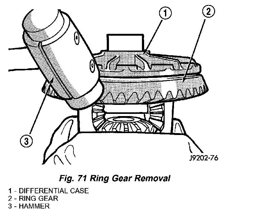
7. Drive ring gear from differential case with a rawhide hammer (Fig. 71).
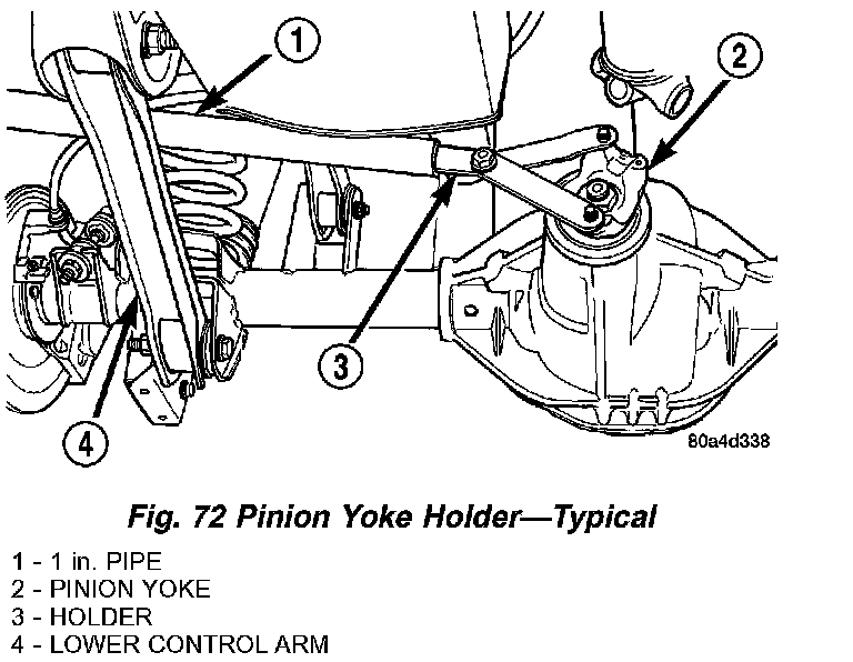
8. Hold the pinion yoke with Spanner Wrench 6958 and remove the pinion yoke nut and washer (Fig. 72).
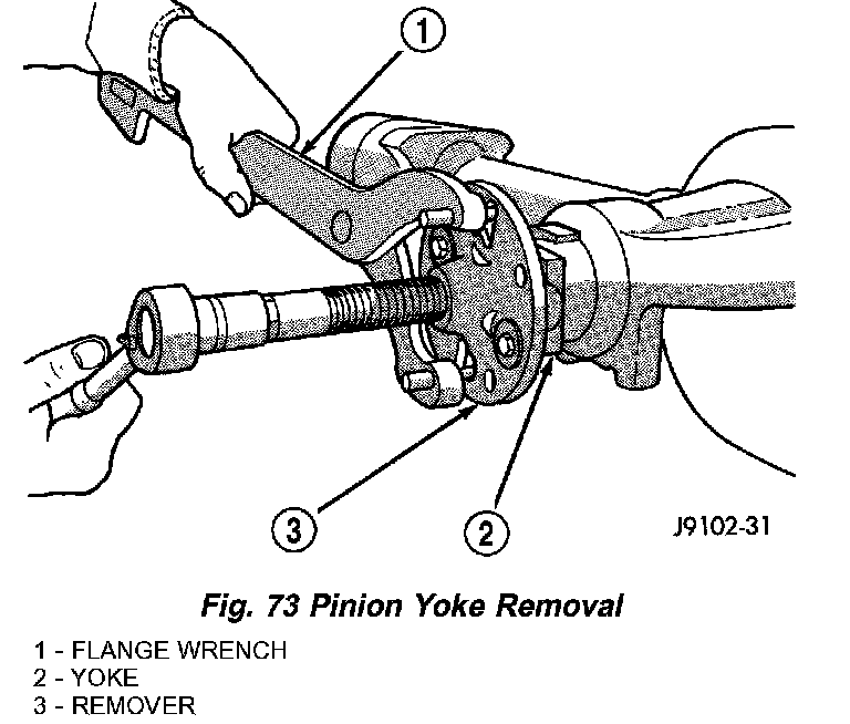
9. Remove pinion yoke from pinion shaft with Remover C-452 and Flange Wrench C-3281 (Fig. 73).
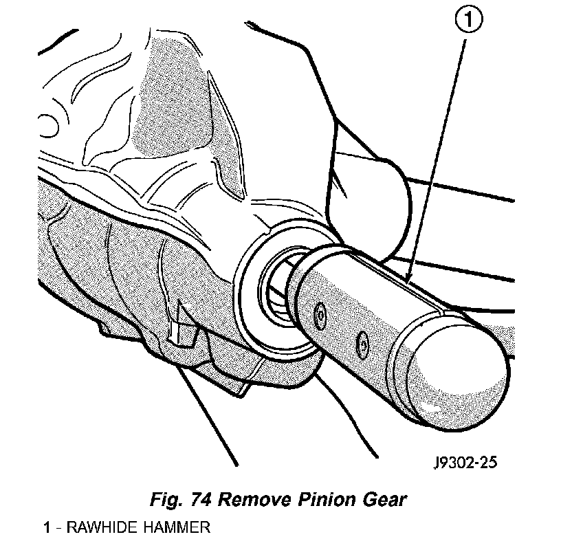
10. Remove pinion gear from housing (Fig. 74).
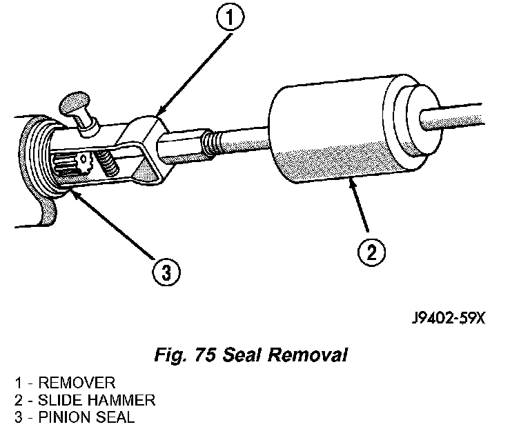
11. Remove pinion seal with Remover 7794-A and a slide hammer (Fig. 75).
12. Remove oil slinger, if equipped, and front pinion bearing.
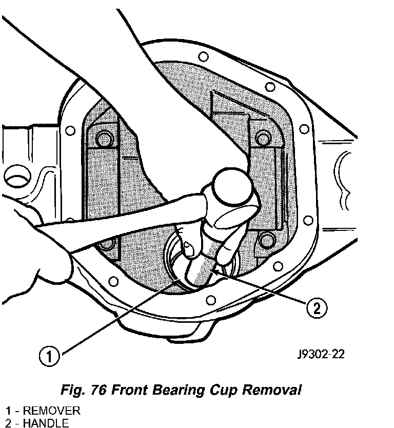
13. Remove front pinion bearing cup with Remover C-4345 and Handle C-4171 (Fig. 76).
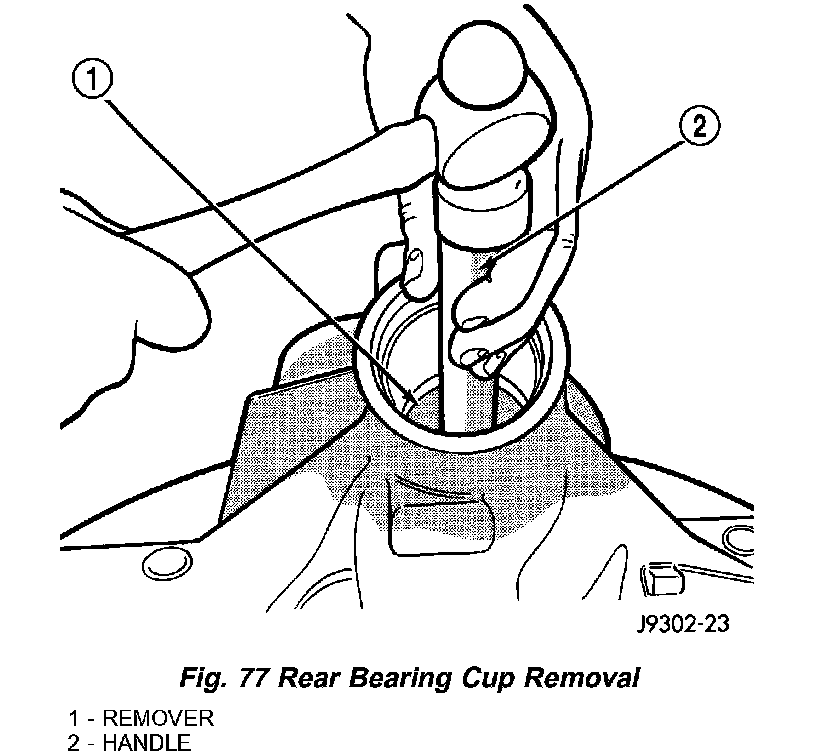
14. Remove rear bearing cup (Fig. 77) with Remover D-149 and Handle C-4171.
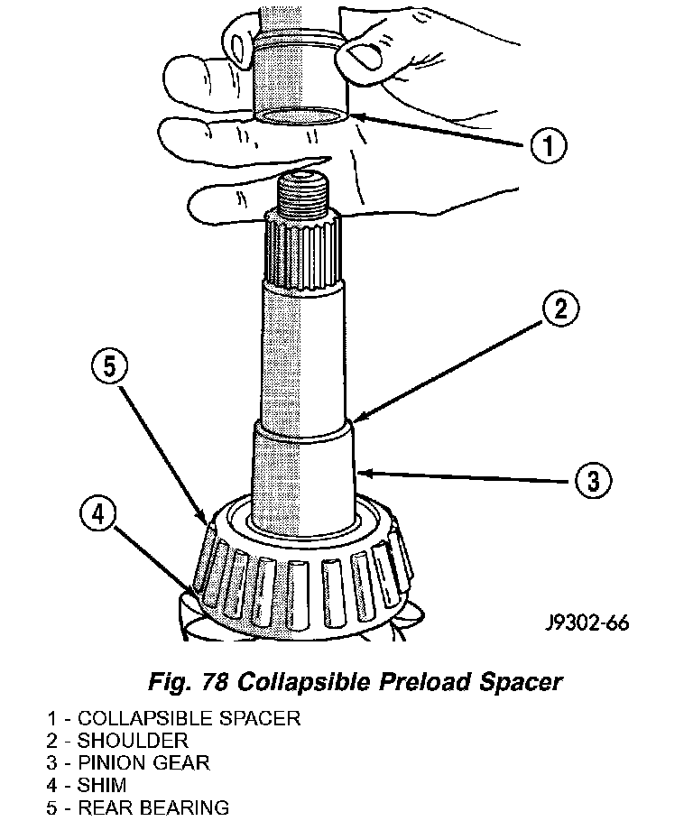
15. Remove collapsible preload spacer (Fig. 78).
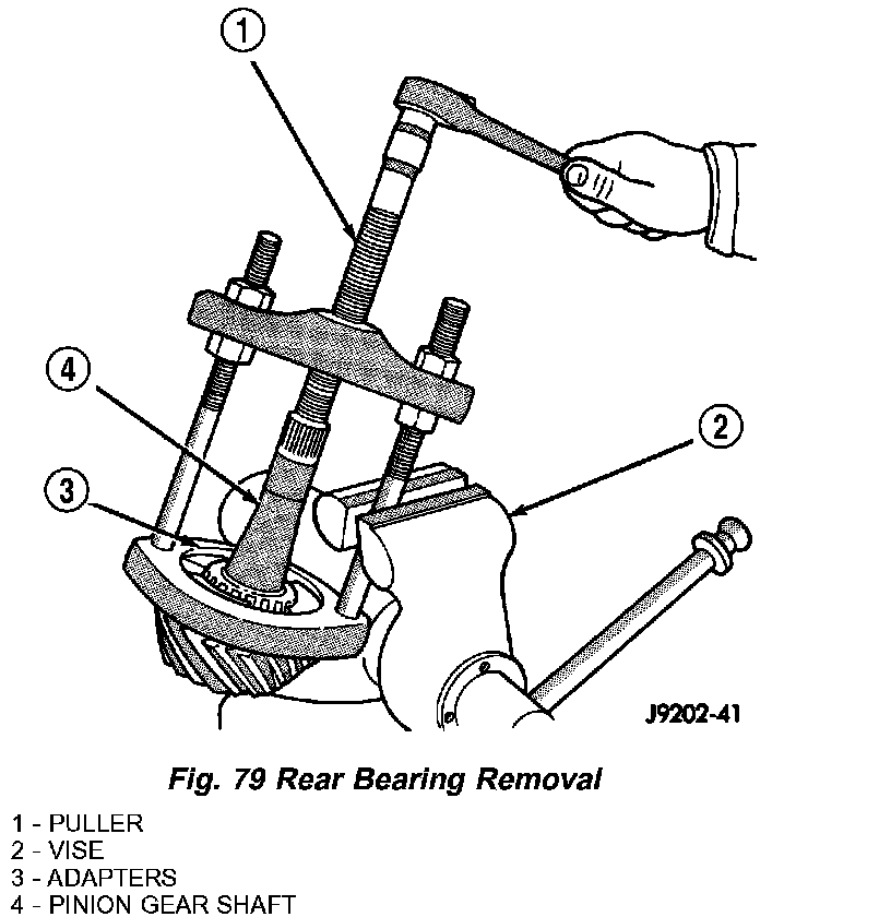
16. Remove rear bearing from the pinion with Puller/Press C-293-PA and Adapters C-293-40 (Fig. 79).
17. Remove depth shims from the pinion gear shaft and record shim thickness.
INSTALLATION
NOTE: A pinion depth shim/oil slinger is placed between the rear pinion bearing cone and the pinion head to achieve proper ring gear and pinion mesh. If ring gear and pinion are reused, the pinion depth shim/oil slinger should not require replacement. Refer to Adjustment (Pinion Gear Depth) to select the proper thickness shim/oil slinger if ring and pinion gears are replaced.
1. Apply Mopar Door Ease or equivalent lubricant to outside surface of the pinion bearing cups.
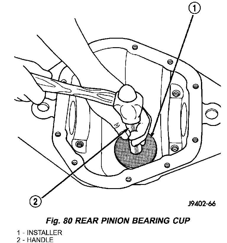
2. Install pinion rear bearing cup with Installer D-146 and Driver Handle C-4171 (Fig. 80) and verify cup is seated.
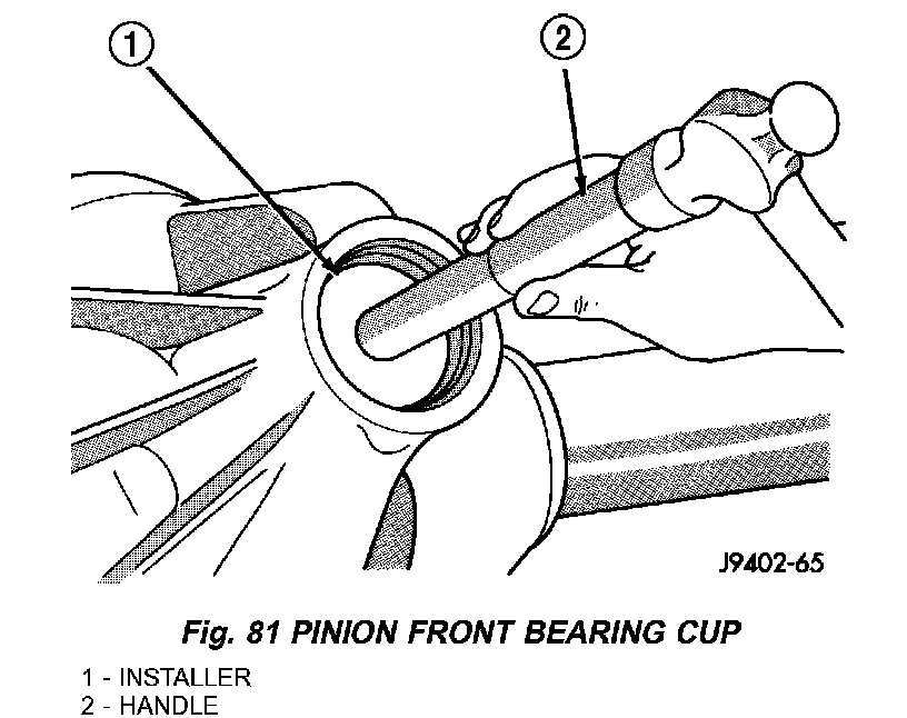
3. Install pinion front bearing cup with Installer D-130 and Handle C-4171 (Fig. 81) and verify cup is seated.
4. Install pinion front bearing and oil slinger, if equipped.
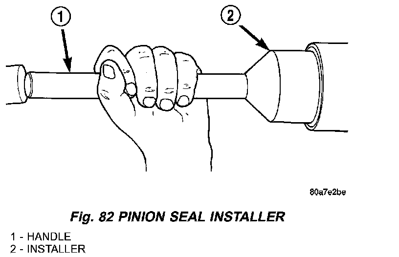
5. Apply a light coating of gear lubricant on the lip of pinion seal. Install seal with an appropriate installer (Fig. 82).
6. Install depth shim on the pinion gear.
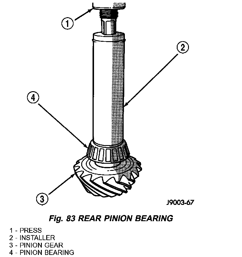
7. Install rear bearing and slinger if equipped, on the pinion gear with Installer W-262 and a press (Fig. 83).
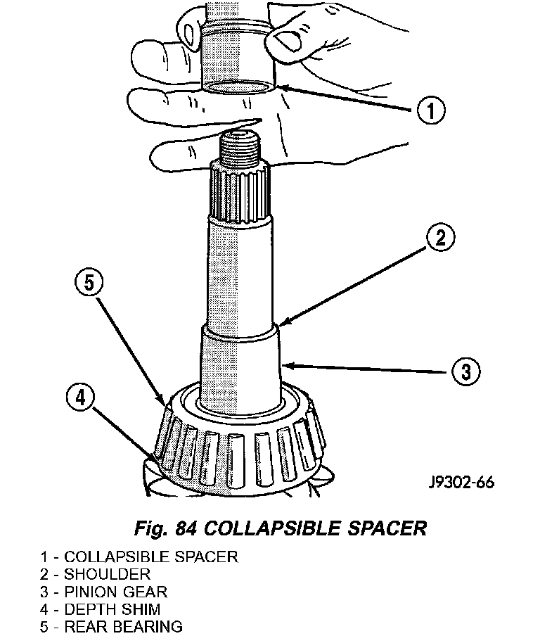
8. Install a new collapsible preload spacer on pinion shaft and install pinion gear in the housing (Fig. 84).
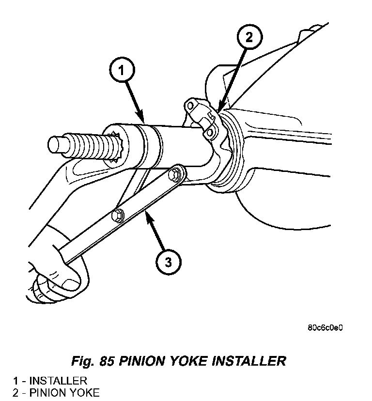
9. Install yoke with Installer C-3718 and Spanner Wrench 6958 (Fig. 85).
10. Install the yoke washer and a new nut on the pinion gear and tighten the pinion nut until there is zero bearing end-play.
11. Tighten the nut to 271 Nm (200 ft. lbs.).
CAUTION: Never loosen pinion gear nut to decrease pinion rotating torque and never exceed specified preload torque. If preload torque or rotating torque is exceeded a new collapsible spacer must be installed.
NOTE: New collapsible spacers require high initial torque to start the collapsing of the spacer. This may reach 678 Nm (500 ft. lbs.).
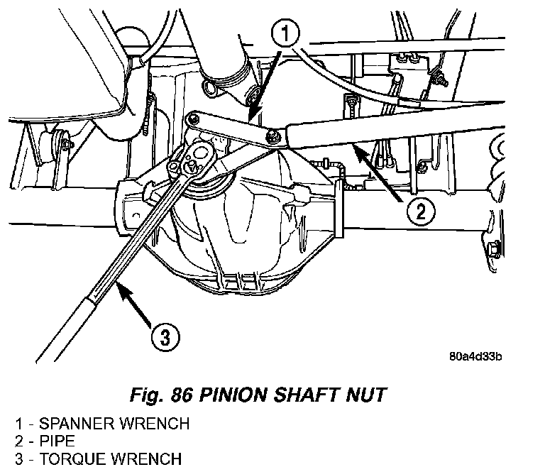
12. Using Spanner Wrench 6958 and a torque wrench set at 474 Nm (350 ft. lbs.), (Fig. 86) slowly tighten the nut in 6.8 Nm (5 ft. lbs.) increments until the rotating torque is achieved. Measure the rotating torque frequently to avoid over crushing the collapsible spacer (Fig. 87).
NOTE: If more than 474 Nm (350 ft. lbs.) torque is required to crush the collapsible spacer, the spacer is defective and must be replaced.
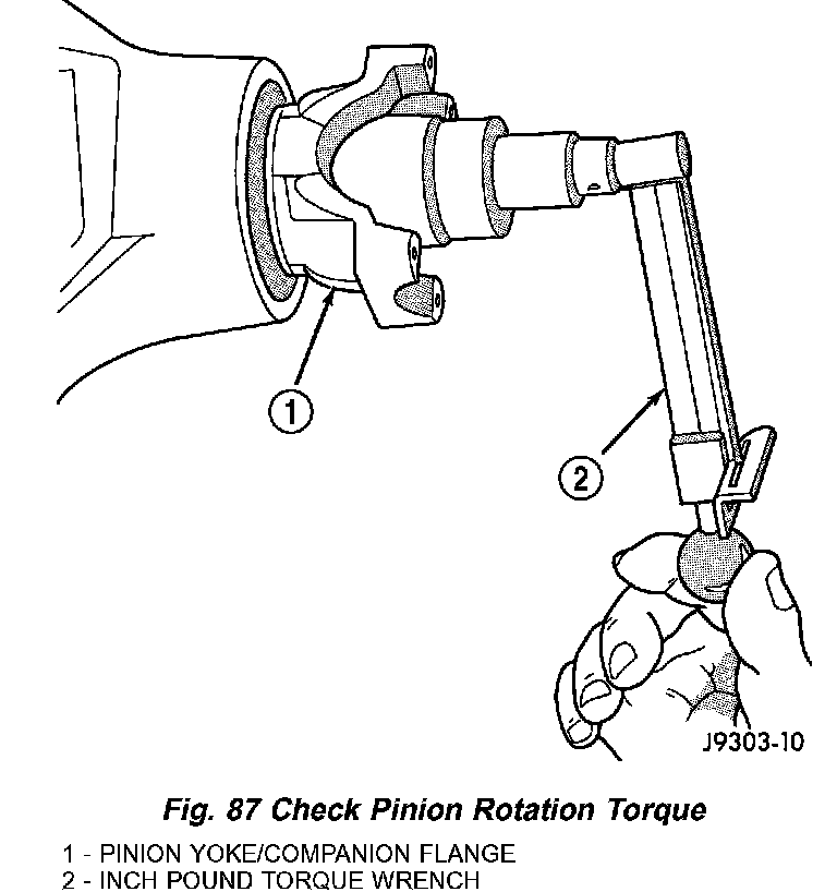
13. Check bearing rotating torque with a inch pound torque wrench (Fig. 87). The pinion gear rotating torque should be:
- Original Bearings: 1 - 2.25 Nm (10 - 20 in. lbs.).
- New Bearings: 1.7 - 3.9 Nm (15 - 35 in. lbs.).
14. Invert the differential case and start two ring gear bolts. This will provide case-to-ring gear bolt hole alignment.
15. Invert the differential case in the vise.
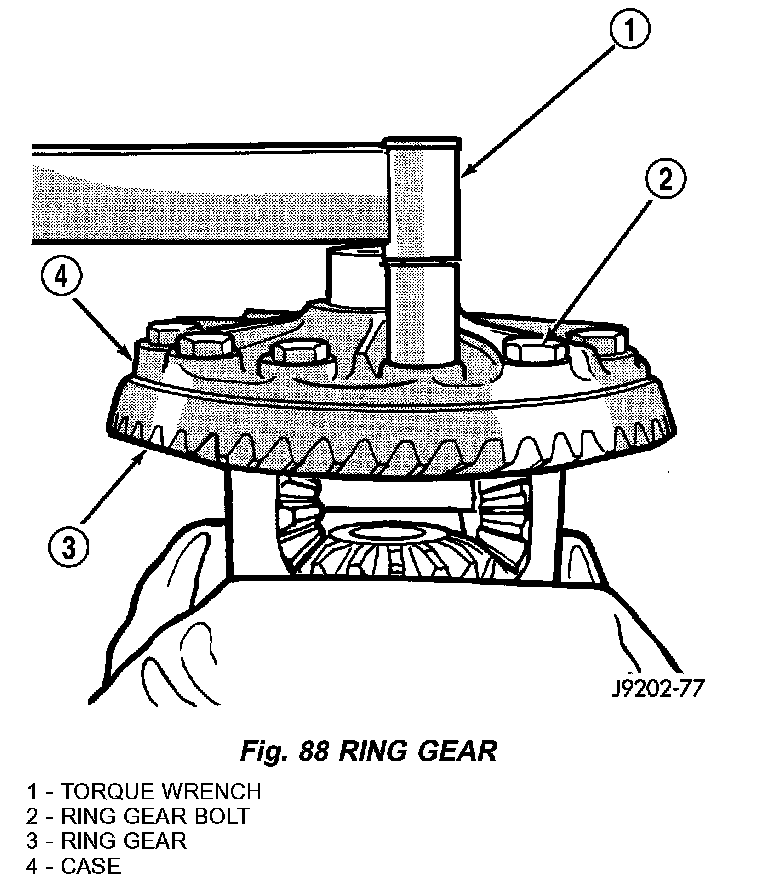
16. Install new ring gear bolts and alternately tighten to 136 Nm (100 ft. lbs.) (Fig. 88).
CAUTION: Never reuse the ring gear bolts. The bolts can fracture causing extensive damage.
17. Install differential in housing and verify differential bearing preload, gear mesh and contact pattern. Refer to Adjustments for procedure.
18. Install differential cover and fill with gear lubricant.
19. Install the propeller shaft with the reference marks aligned.
20. Remove supports and lower vehicle.