Part 4
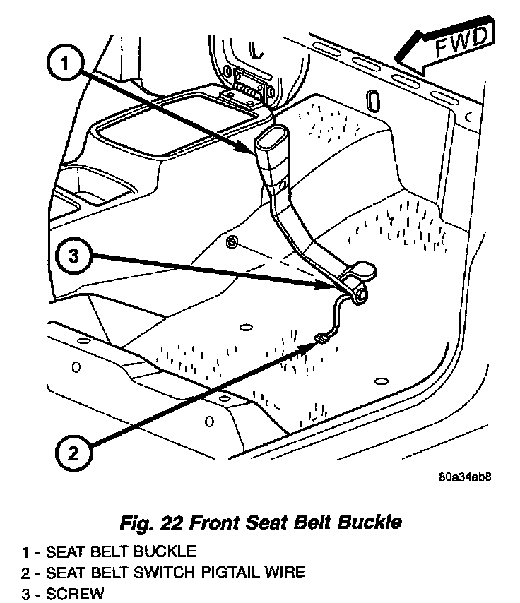
Fig.22 Front Seat Belt Buckle:
SEAT BELT SWITCH
The seat belt switch for this model is actually a Hall Effect-type sensor. This sensor consists of a fixed-position, Hall Effect Integrated Circuit (IC) chip and a small permanent magnet that are integral to each front seat belt buckle. The front seat belt buckles are each located on a stamped steel stanchion within a molded plastic scabbard and secured with a screw to the floor panel transmission tunnel on the inboard side of each front seat cushion. The seat belt switches are connected to the vehicle electrical system through a two-lead pigtail wire and connector on the seat belt buckle-half, which is connected to a wire harness connector and take out of the body wire harness on vehicles with manual seat adjusters, or to a connector and take out of the power seat wire harness on vehicles with power seat adjusters. A radio noise suppression capacitor is connected in parallel with the IC where the two pigtail wire leads connect to the IC pins.
The seat belt switch cannot be adjusted or repaired and, if faulty or damaged, the entire seat belt buckle-half unit must be replaced.
The seat belt switches are designed to provide a status signal to the seat belt switch sense inputs of the Airbag Control Module (ACM) indicating whether the front seat belts are fastened. The ACM uses the seat belt switch inputs as a factor in determining what level of force with which it should deploy the multistage driver and passenger airbags. In addition, the ACM sends electronic messages to the ElectroMechanical Instrument Cluster (EMIC) to control the seat belt indicator based upon the status of the driver side front seat belt switch. A spring-loaded slide with a small window-like opening is integral to the buckle latch mechanism. When a seat belt tip- half is inserted and latched into the seat belt buckle, the slide is pushed downward and the window of the slide exposes the Hall Effect Integrated Circuit (IC) chip within the buckle to the field of the permanent magnet, which induces a current within the chip. The chip provides this induced current as an output to the ACM, which monitors the current to determine the status of the front seat belts. When the seat belt is unbuckled, the spring-loaded slide moves upward and shields the IC from the field of the permanent magnet, causing the output current from the seat belt switch to be reduced.
The seat belt switch receives a supply current from the ACM, and the ACM senses the status of the front seat belts through its pigtail wire connection to the airbag overlay wire harness. The ACM monitors the condition of the seat belt switch circuits and will illuminate the airbag indicator in the EMIC then store a Diagnostic Trouble Code (DTC) for any fault that is detected in either seat belt switch circuit. For proper diagnosis of the seat belt switches, a DRB III scan tool is required. Refer to the appropriate diagnostic information.
SIDE CURTAIN AIRBAG
Fig.2 SRS Logo:
Optional side curtain airbags are available for this model when it is also equipped with dual front airbags. These airbags are passive, inflatable, Supplemental Restraint System (SRS) components, and vehicles with this equipment can be readily identified by a molded identification trim button with the "SRS - AIRBAG" logo located on the headliner above each B-pillar. This system is designed to reduce injuries to the vehicle occupants in the event of a side impact collision.
Fig.43 Side Curtain Airbag:
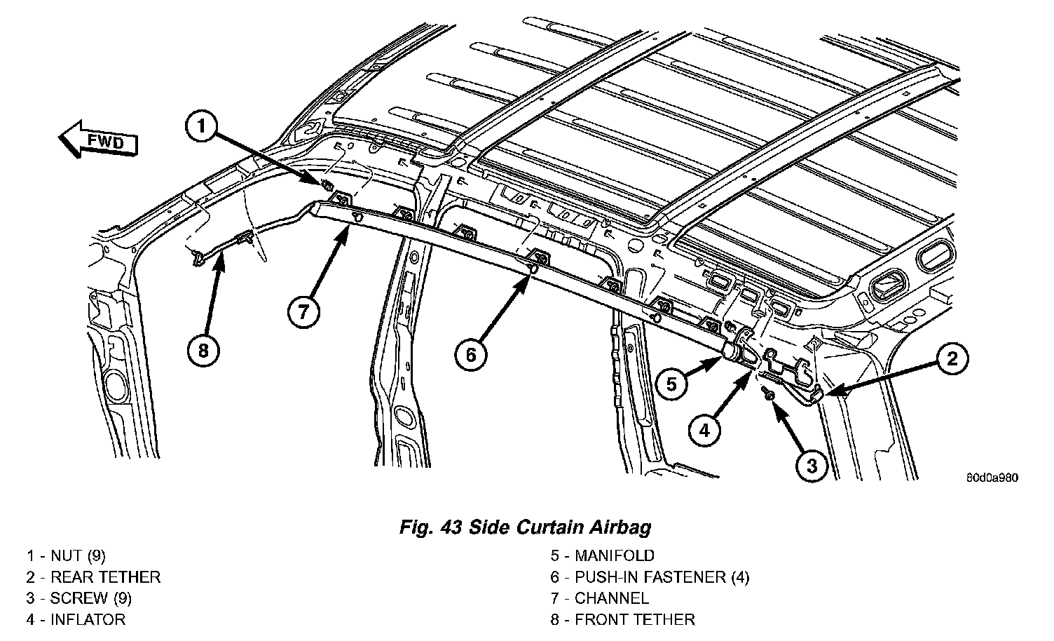
Vehicles equipped with side curtain airbags have two individually controlled curtain airbag units. These airbag units are concealed and mounted above the headliner where they are each secured to one of the roof side rails. Each folded airbag cushion is contained within a long extruded plastic channel that extends along the roof rail from the A-pillar at the front of the vehicle to just behind the C-pillar at the rear of the vehicle. One tether extends down the A-pillar from the front of the airbag cushion, and a second tether extends to the roof rail above the D-pillar. The ends of these tethers are secured to slots in the sheet metal with metal hooks retained by plastic anchor clips.
The hybrid-type inflator for each airbag is secured to the roof rail at the rear of the airbag unit between the C-pillar and the D-pillar, and is connected to the airbag cushion by a long tubular manifold. The inflator bracket and the extruded airbag cushion channel are secured with both plastic push-in fasteners and screws to the roof rail. A dedicated two-wire take out and connector of the body wire harness is routed forward from the D-pillar to the airbag inflator.
The side curtain airbag unit cannot be adjusted or repaired and must be replaced if deployed, faulty, or in any way damaged. Once a side curtain airbag has been deployed, the complete airbag unit, the headliner, the upper A, B, and C-pillar trim, and all other visibly damaged components must be replaced.
Each side curtain airbag is deployed individually by an electrical signal generated by the Airbag Control Module (ACM) to which it is connected through left or right curtain airbag line 1 and line 2 (or squib) circuits. The hybrid-type inflator assembly for each airbag contains a small canister of highly compressed gas. When the ACM sends the proper electrical signal to the airbag inflator, the electrical energy creates enough heat to ignite chemical pellets within the inflator. Once ignited, these chemicals burn rapidly and produce the pressure necessary to rupture a containment disk in the pressurized gas canister. The inflator and gas canister are sealed and connected to a tubular manifold so that all of the released inert gas is directed into the folded side curtain airbag cushion, causing the cushion to inflate.
As the airbag cushion inflates it will drop down from the roof rail between the edge of the headliner and the side glass/body pillars to form a curtain-like cushion to protect the vehicle occupants during a side impact collision. The front and rear tethers keep the side curtain bag taut, thus ensuring that the bag will deploy in the proper position. Following the airbag deployment, the airbag cushion quickly deflates by venting the inert gas through the loose weave of the cushion fabric, and the deflated cushion hangs down loosely from the roof rail.
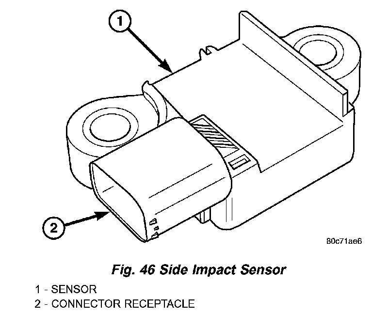
Fig.46 Side Impact Sensor:
SIDE IMPACT SENSOR
Two side impact sensors are used on this model when it is equipped with the optional side curtain airbags, one each for the left and right sides of the vehicle. These sensors are mounted remotely from the bi-directional safing sensor that is internal to the Airbag Control Module (ACM). The side and front impact sensors are identical in construction and calibration with the exception of the right-hand and left-hand die cast aluminum mounting brackets to which each front impact sensor is secured with two screws. The side impact sensors are secured with two screws to the base of the right and left B-pillars just below the front seat belt retractors and behind the lower B-pillar trim within the passenger compartment.
The impact sensor housing has an integral connector receptacle and two integral mounting ears, each with a metal sleeve to provide crush protection. A cavity in the center of the molded black plastic impact sensor housing contains the electronic circuitry of the sensor which includes an electronic communication chip and an electronic impact sensor. Potting material fills the cavity to seal and protect the internal electronic circuitry and components. The side impact sensors are each connected to the vehicle electrical system through a dedicated take out and connector of the airbag overlay wire harness.
The side impact sensors cannot be repaired or adjusted and, if damaged or faulty, they must be replaced.
The side impact sensors are electronic accelerometers that sense the rate of vehicle deceleration, which provides verification of the direction and severity of an impact. Each sensor also contains an electronic communication chip that allows the unit to communicate the sensor status as well as sensor fault information to the microprocessor in the Airbag Control Module (ACM). The ACM microprocessor continuously monitors all of the passive restraint system electrical circuits to determine the system readiness. If the ACM detects a monitored system fault, it sets a Diagnostic Trouble Code (DTC) and controls the airbag indicator operation accordingly
The impact sensors each receive battery current and ground through dedicated left and right sensor plus and minus circuits from the ACM. The impact sensors and the ACM communicate by modulating the voltage in the sensor plus circuit. The hard wired circuits between the side impact sensors and the ACM may be diagnosed and tested using conventional diagnostic tools and procedures. However, conventional diagnostic methods will not prove conclusive in the diagnosis of the ACM or the impact sensors. The most reliable, efficient, and accurate means to diagnose the impact sensors, the ACM, and the electronic message communication between the sensors and the ACM requires the use of a DRB III scan tool. Refer to the appropriate diagnostic information.