Clockspring Assembly / Spiral Cable: Service and Repair
CLOCKSPRINGThe clockspring cannot be repaired. It must be replaced if faulty or damaged, or if the driver airbag has been deployed.
NOTE: Before starting this procedure, be certain to turn the steering wheel until the front wheels are in the straight-ahead position.
WARNING: ON VEHICLES EQUIPPED WITH AIRBAGS, DISABLE THE SUPPLEMENTAL RESTRAINT SYSTEM BEFORE ATTEMPTING ANY STEERING WHEEL, STEERING COLUMN, DRIVER AIRBAG, PASSENGER AIRBAG, FRONT IMPACT SENSOR, SIDE IMPACT SENSOR, SIDE CURTAIN AIRBAG, OR INSTRUMENT PANEL COMPONENT DIAGNOSIS OR SERVICE. DISCONNECT AND ISOLATE THE BATTERY NEGATIVE (GROUND) CABLE, THEN WAIT TWO MINUTES FOR THE SYSTEM CAPACITOR TO DISCHARGE BEFORE PERFORMING FURTHER DIAGNOSIS OR SERVICE. THIS IS THE ONLY SURE WAY TO DISABLE THE SUPPLEMENTAL RESTRAINT SYSTEM. FAILURE TO TAKE THE PROPER PRECAUTIONS COULD RESULT IN ACCIDENTAL AIRBAG DEPLOYMENT AND POSSIBLE PERSONAL INJURY.
REMOVAL
1. Place the front wheels in the straight ahead position.
2. Remove the driver airbag from the steering wheel.
3. Disconnect the steering wheel wire harness connectors from the upper clockspring connector receptacles.
4. Remove the steering wheel from the steering column.
Fig. 18 Steering Column Shrouds Remove/Install:
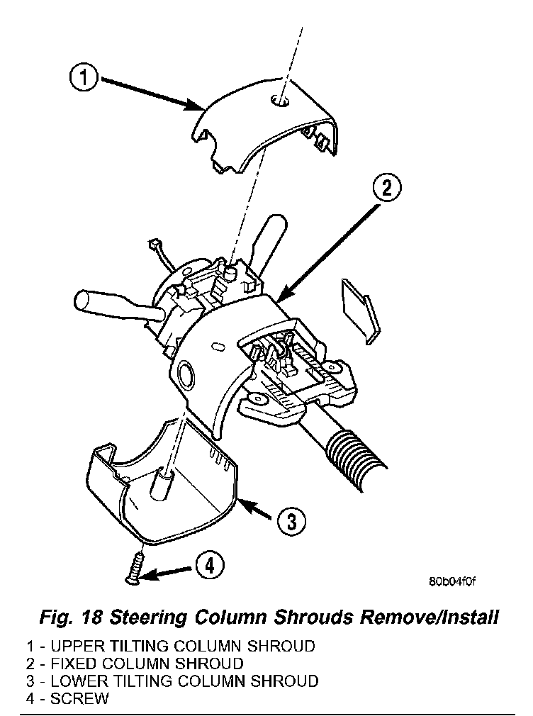
5. From below the steering column, remove the screw that secures the lower tilting steering column shroud to the steering column multi-function switch mounting housing.
6. Using hand pressure, push gently inward on both sides of the upper shroud near the parting line between the upper and lower shrouds to release the snap features that secure the two halves to each other.
7. Remove both the upper and lower shrouds from the steering column.
8. Disconnect the two instrument panel wire harness connectors for the clockspring from the two connector receptacles below the steering column on the back of the clockspring case.
Fig. 19 Clockspring Remove/Install:
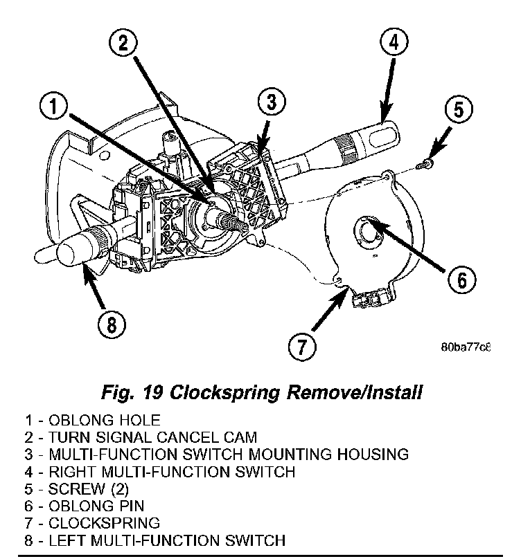
9. Remove the two screws that secure the clockspring case to the multi-function switch mounting housing.
10. Remove the clockspring from the multi-function switch mounting housing. The clockspring cannot be repaired. It must be replaced if faulty or damaged, or if the driver airbag has been deployed.
11. If the removed clockspring is to be reused, be certain to secure the clockspring rotor to the clockspring case to maintain clockspring centering until it is reinstalled on the steering column. If clockspring centering is not maintained, the clockspring must be centered again before it is reinstalled.
INSTALLATION
If the clockspring is not properly centered in relation to the steering wheel, steering shaft and steering gear, it may be damaged. Service replacement clocksprings are shipped pre-centered and with a locking pin installed. This locking pin should not be removed until the clockspring has been installed on the steering column. If the locking pin is removed before the clockspring is installed on a steering column, the clockspring centering procedure must be performed.
1. While holding the centered clockspring rotor and case stationary in relation to each other, carefully slide the clockspring down over the steering column upper shaft.
2. Align and seat the three pins on the lower surface of the clockspring rotor hub with the three holes in the hub of the turn signal cancel cam. It should be noted that when the clockspring is properly centered the uppermost pin on the clockspring rotor hub is the oblong pin, and it will only fit in the oblong hole in the hub of the turn signal cancel cam.
3. Align and seat the one pin and the two mounting ears on the clockspring case to their respective holes in the multi-function switch mounting housing.
4. Install and tighten the two clockspring mounting screws. Tighten the screws to 2.5 Nm (22 in. lbs.).
5. Reconnect the two instrument panel wire harness connectors for the clockspring to the two connector receptacles below the steering column on the back of the clockspring housing.
6. Position the lower tilting steering column shroud onto the steering column.
7. Install and tighten the screw that secures the lower tilting steering column shroud to the multi-function switch mounting housing. Tighten the screw to 2 Nm (17 in. lbs.).
8. Position the upper tilting column shroud onto the steering column with the hazard warning switch button inserted through the hole in the upper surface of the shroud.
9. Align the snap features on the upper and lower shrouds and apply hand pressure to snap them together.
10. If a new clockspring has been installed, remove the plastic locking pin that secures the clockspring rotor to the clockspring case to maintain clockspring centering.
11. Reinstall the steering wheel onto the steering column.
12. Reconnect the steering wheel wire harness connectors to the upper clockspring connector receptacles.
13. Reinstall the driver airbag onto the steering wheel.