Driver/Passenger Airbags
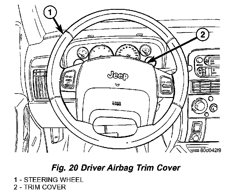
Fig. 20 Driver Airbag Trim Cover:
DRIVER AIRBAG
The injection molded, thermoplastic driver airbag protective trim cover is the most visible part of the driver airbag. The driver airbag is located in the center of the steering wheel, where it is secured with two screws to the two horizontal spokes of the four-spoke steering wheel armature. A stamped, satin polished emblem with the Jeep logo is applied to the center of the trim cover. Concealed beneath the driver airbag trim cover are the horn switch, the folded airbag cushion, the airbag cushion retainer, the airbag housing, the airbag inflator, and the retainers that secure the inflator to the airbag housing.
The airbag cushion, housing, and inflator are secured within an integral receptacle molded into the back of the trim cover. Locking blocks molded into the back of the trim cover around the receptacle engage a lip formed around the perimeter of the airbag housing stamping. Two stamped metal retainers then fit over the inflator mounting studs on the back of the airbag housing and are engaged in slots within the upper and lower trim cover locking blocks, securely locking the cover into place.
The resistive membrane-type horn switch is secured within a plastic tray that is inserted in a pocket or pouch sewn onto the airbag cushion retainer strap, between the trim cover and the folded airbag cushion. The horn switch ground pigtail wire has an eyelet terminal connector that is captured on the upper right inflator mounting stud between the inflator and the upper trim cover retainer. The horn switch feed pigtail wire has a white, molded plastic insulator that is secured by an integral retainer to a mounting hole located in the upper trim cover retainer near the upper left corner on the back of the airbag housing, and is connected to the vehicle electrical system through a take out and connector of the steering wheel wire harness.
The airbag used in this model is a multistage, Next Generation-type that complies with revised federal airbag standards to deploy with less force than those used in some prior models. A radial deploying fabric airbag cushion with internal tethers is used. The airbag inflator is a dual-initiator, non-azide, pyrotechnic-type unit with four mounting studs and is secured to the stamped metal airbag housing using four hex nuts with washers. Two keyed and color- coded connector receptacles on the driver airbag inflator connect the two inflator initiators to the vehicle electrical system through two yellow-jacketed, two-wire pigtail harnesses of the clockspring. The driver airbag cannot be repaired, and must be replaced if deployed or in any way damaged. The driver airbag trim cover and the horn switch are available for individual service replacement.
The multistage driver airbag is deployed by electrical signals generated by the Airbag Control Module (ACM) through the driver airbag squib 1 and squib 2 circuits to the two initiators in the airbag inflator. By using two initiators, the airbag can be deployed at multiple levels of force. The force level is controlled by the ACM to suit the monitored impact conditions by providing one of four delay intervals between the electrical signals provided to the two initiators. The longer the delay between these signals, the less forcefully the airbag will deploy
When the ACM sends the proper electrical signals to each initiator, the electrical energy generates enough heat to initiate a small pyrotechnic charge which, in turn ignites chemical pellets within the inflator. Once ignited, these chemical pellets burn rapidly and produce a large quantity of inert gas. The inflator is sealed to the back of the airbag housing and a diffuser in the inflator directs all of the inert gas into the airbag cushion, causing the cushion to inflate. As the cushion inflates, the driver airbag trim cover will split at predetermined breakout lines, then fold back out of the way along with the horn switch and tray unit. Following an airbag deployment, the airbag cushion quickly deflates by venting the inert gas towards the instrument panel through vent holes within the fabric used to construct the back (steering wheel side) panel of the airbag cushion.
Some of the chemicals used to create the inert gas may be considered hazardous while in their solid state before they are burned, but they are securely sealed within the airbag inflator. Typically, both initiators are used and all potentially hazardous chemicals are burned during an airbag deployment event. However, it is possible for only one initiator to be used during a deployment due to an airbag system fault; therefore, it is necessary to always confirm that both initiators have been used in order to avoid the improper disposal of potentially live pyrotechnic or hazardous materials.
The inert gas that is produced when the chemicals are burned is harmless. However, a small amount of residue from the burned chemicals may cause some temporary discomfort if it contacts the skin, eyes, or breathing passages. If skin or eye irritation is noted, rinse the affected area with plenty of cool, clean water. If breathing passages are irritated, move to another area where there is plenty of clean, fresh air to breath. If the irritation is not alleviated by these actions, contact a physician.
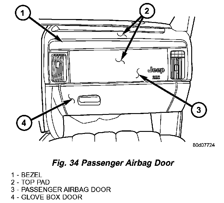
Fig. 34 Passenger Airbag Door:
PASSENGER AIRBAG
The rearward facing surface of the instrument panel top pad above the glove box is the most visible part of the passenger airbag. The passenger airbag door is concealed behind the instrument panel top pad and above the glove box opening on the instrument panel in front of the front seat passenger seating position. The stamped steel passenger airbag door is secured on the back of the instrument panel top pad armature between the two passenger side panel outlets. A stamped metal reinforcement is secured to the instrument panel top pad armature near the upper edge of the passenger airbag door opening, and helps to define a predetermined hinge line beneath the decorative cover of the top pad. The instrument panel passenger side bezel is secured to the top of the airbag door from behind with four screws.
Fig. 35 Passenger Airbag:
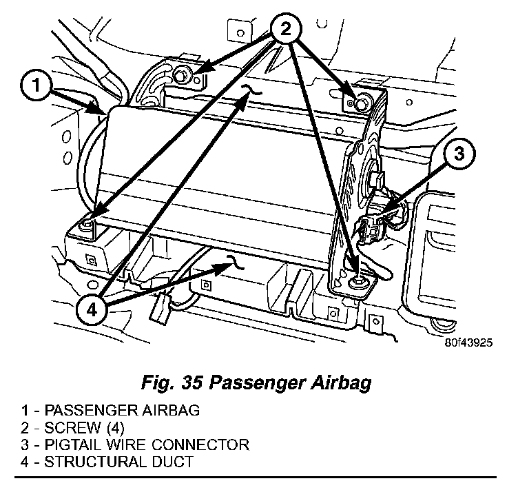
Located behind the passenger airbag door is the passenger airbag unit. The passenger airbag unit is secured by two screws on each side to the instrument panel structural duct. A short four-wire pigtail harness with a keyed, yellow connector insulator connects the two inflator initiators to the vehicle electrical system through a dedicated take out and connector of the instrument panel wire harness.
The passenger airbag unit used in this model is a multistage, Next Generation-type that complies with revised federal airbag standards to deploy with less force than those used in some prior models. The passenger airbag unit consists of an extruded aluminum housing, two stamped steel end brackets, a molded plastic inner airbag cushion cover, the rectangular fabric airbag cushion, and the airbag inflator. The airbag housing contains the airbag inflator, while the inner cover contains the folded airbag cushion. The inner cover completely encloses the airbag cushion and is permanently retained to the housing. The air- bag cushion is constructed of a coated nylon fabric. The airbag inflator is a dual-initiator, hybrid-type unit that is secured to and sealed within the airbag housing.
The passenger airbag cannot be repaired, and must be replaced if deployed, faulty, or in any way damaged. The passenger airbag door is serviced only as a unit with the instrument panel top pad. If the passenger airbag is deployed, the instrument panel top pad must also be replaced. If inspection reveals that the passenger airbag mounting points on the instrument panel structural duct have been cracked or damaged by the deployment event, the instrument panel structural duct assembly must also be replaced.
The multistage passenger airbag is deployed by electrical signals generated by the Airbag Control Module (ACM) through the passenger airbag squib 1 and squib 2 circuits to the two initiators in the airbag inflator. By using two initiators, the airbag can be deployed at multiple levels of force. The force level is controlled by the ACM to suit the monitored impact conditions by providing one of four delay intervals between the electrical signals provided to the two initiators. The longer the delay between these signals, the less forcefully the airbag will deploy.
The hybrid-type inflator assembly includes a small canister of highly compressed gas. When the ACM sends the proper electrical signal to the airbag initiator, the initiator generates enough heat to ignite chemical pellets within the inflator. Once ignited, these chemical pellets burn rapidly and produce the pressure necessary to rupture a containment disk in the pressurized gas canister. The inflator and gas canister are sealed to the airbag cushion so that all of the released inert gas is directed into the airbag cushion, causing the cushion to inflate. As the cushion inflates, the passenger airbag door will bend back the instrument panel top pad at the predetermined hinge line, then fold back over the top of the instrument panel and out of the way. Following a passenger airbag deployment, the airbag cushion quickly deflates by venting the inert gas through vent holes within the fabric used to construct the sides of the airbag cushion.
Typically, both initiators are used during an airbag deployment event. However, it is possible for only one initiator to be used during a deployment due to an airbag system fault; therefore, it is necessary to always confirm that both initiators have been used in order to avoid the improper disposal of potentially live pyrotechnic materials.