Fuel Delivery and Air Induction: Testing and Inspection
VISUAL INSPECTIONA visual inspection for loose, disconnected or incorrectly routed wires, vacuum lines and hoses should be made. This should be done before attempting to diagnose or service the fuel injection system. A visual check will help spot these faults and save unnecessary test and diagnostic time. A thorough visual inspection will include the following checks:
Fig. 1 Powertrain Control Module (PCM) Location:
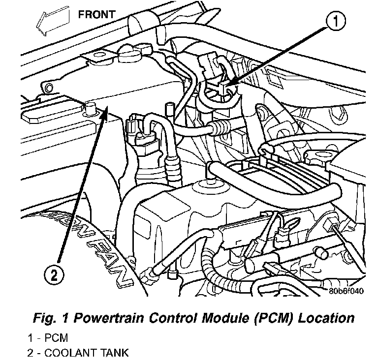
1. Verify three 32-way electrical connectors are fully inserted into connector of Powertrain Control Module (PCM) (Fig. 1).
2. Inspect battery cable connections. Be sure they are clean and tight.
Fig. 2 Power Distribution Center (PDC) Location:
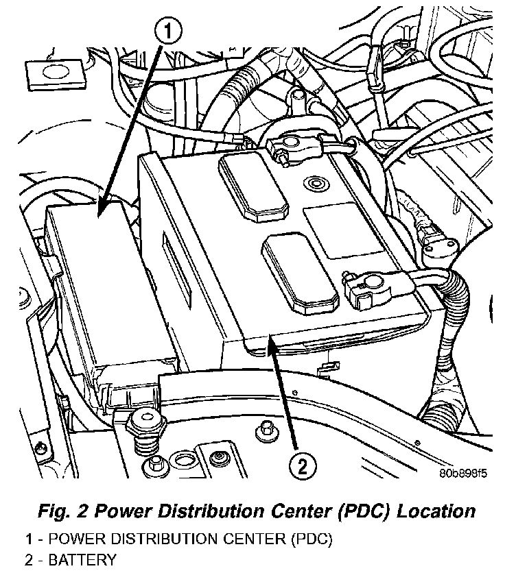
3. Inspect fuel pump relay and air conditioning compressor clutch relay (if equipped). Inspect ASD and oxygen sensor heater relay connections. Inspect starter motor relay connections. Inspect relays for signs of physical damage and corrosion. The relays are located in the Power Distribution Center (PDC) (Fig. 2). Refer to label on PDC cover for relay location.
Fig. 3 Ignition Coil Connector - 4.0L Engine:
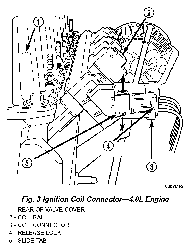
Fig. 4 Ignition Coil Connector - 4.7L V-8 Engine:
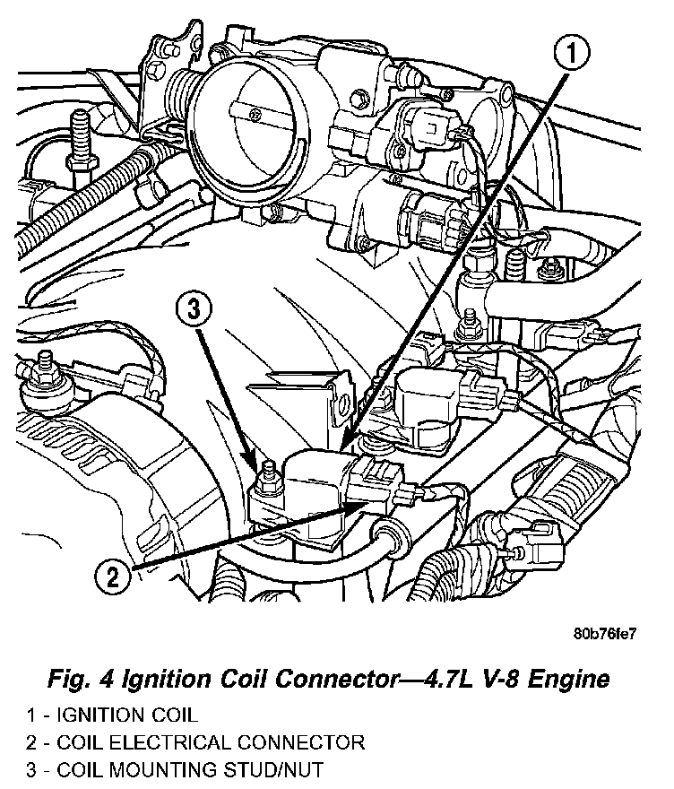
4. Inspect ignition coil connections (Fig. 3) or (Fig. 4).
Fig. 5 Camshaft Position Sensor - 4.0L Engine:
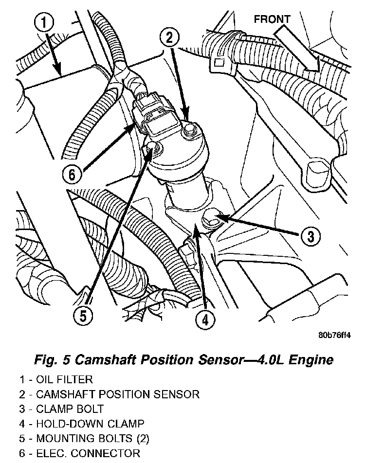
Fig. 6 Camshaft Position Sensor - 4.7L V-8 Engine:
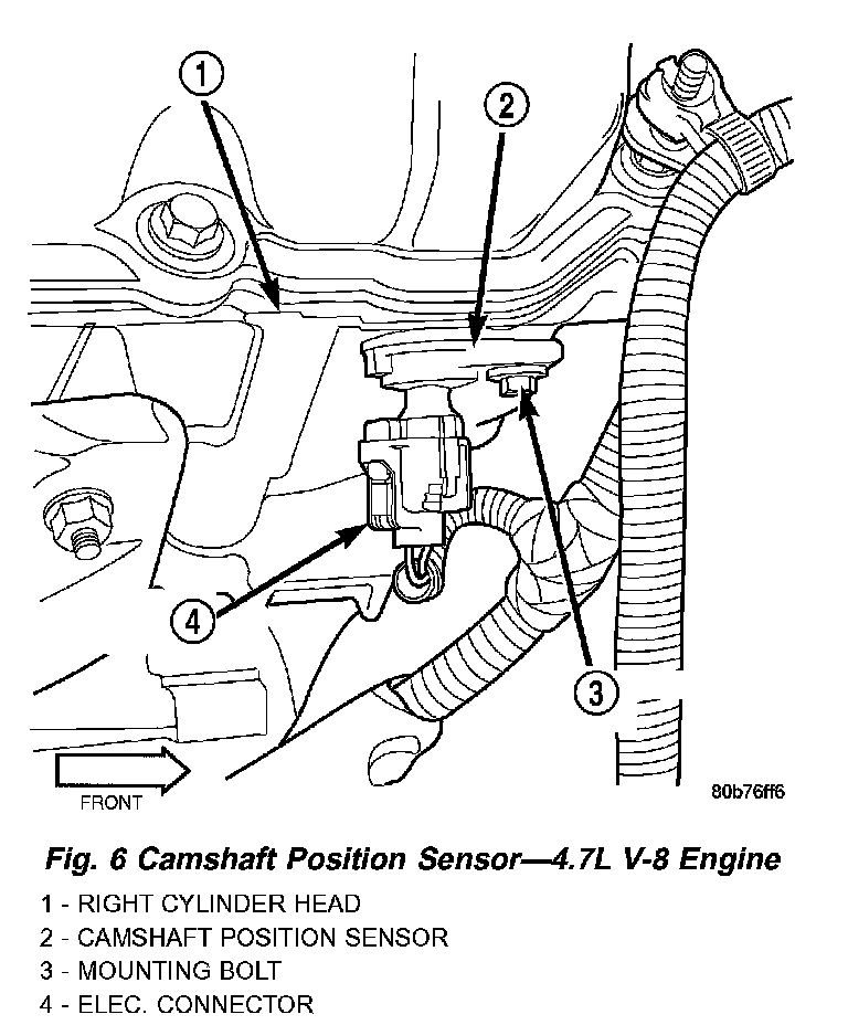
5. Verify camshaft position sensor wire connector is firmly connected (Fig. 5) or (Fig. 6).
Fig. 7 Crankshaft Position Sensor - 4.0L Engine:
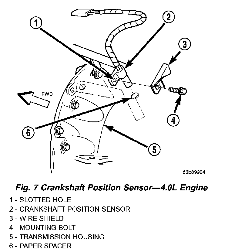
Fig. 8 Crankshaft Position Sensor - 4.7L V-8 Engine:
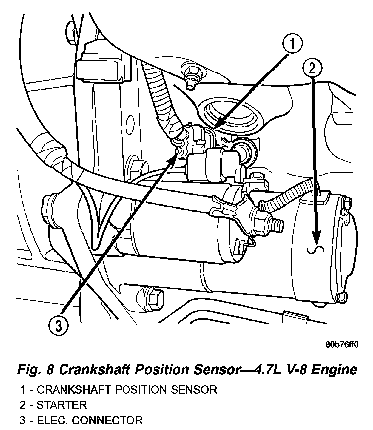
6. Verify crankshaft position sensor wire connector is firmly connected (Fig. 7) or (Fig. 8).
7. Verify generator output wire (B+ wire) and generator field connector are firmly connected to generator.
8. Inspect system body grounds for loose or dirty connections.
9. Verify Crankcase Ventilation (CCV) operation. Refer to Emission Control System for additional information.
10. Inspect all fuel line quick-connect fittings for damage or leaks.
11. Verify hose connections to all ports of vacuum fittings on intake manifold, and for emission system are tight and not leaking.
12. Inspect accelerator cable, transmission throttle cable (if equipped) and speed control cable connections (if equipped). Check their connections to throttle body linkage for any binding or restrictions.
13. Verify vacuum booster hose is firmly connected to fitting on intake manifold. Also check connection to brake vacuum booster.
14. Inspect air cleaner inlet and air cleaner element for dirt or restrictions.
15. Inspect radiator grille area, radiator fins and air conditioning condenser for restrictions.
Fig. 9 IAT, MAP, IAC, TPS Sensor Locations - 4.0L Engine:
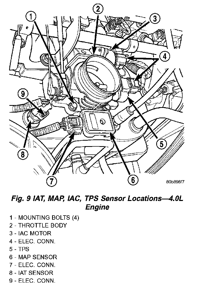
16. 4.0L Engine: Verify MAP, Intake Manifold Air Temperature (IAT) sensor, TPS and Idle Air Control (IAC) motor connectors are firmly connected (Fig. 9). Be sure throttle body mounting bolts (Fig. 9) are tight.
Fig. 10 IAT, IAC, TPS Sensor Locations - 4.7L V-8 Engine:
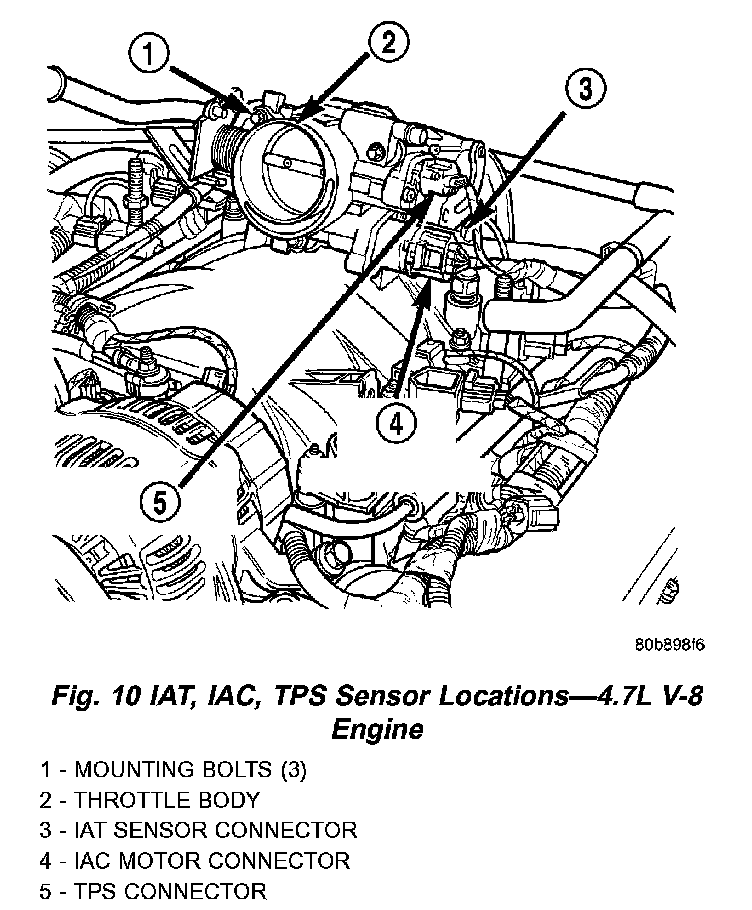
17. 4.7L Engine: Verify Intake Manifold Air Temperature (IAT) sensor, TPS and Idle Air Control (IAC) motor connectors are firmly connected (Fig. 10). Be sure throttle body mounting bolts (Fig. 10) are tight.
Fig. 11 ECT Sensor Location - 4.0L Engine:
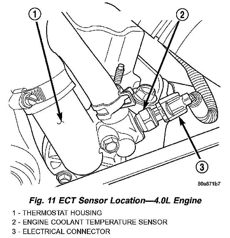
18. 4.0L Engine: Verify wire harness connector is firmly connected to Engine Coolant Temperature (ECT) sensor (Fig. 11).
Fig. 12 MAP And ECT Sensor Locations - 4.7L V-8 Engine:
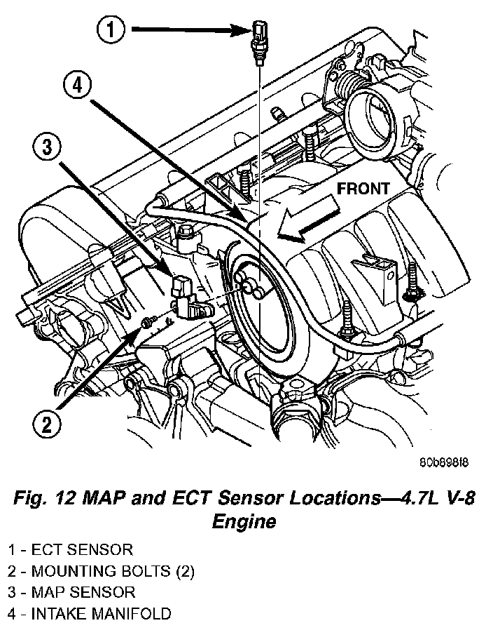
19. 4.7L Engine: Verify MAP and Engine Coolant Temperature (ECT) sensor electrical connectors are firmly connected to sensors (Fig. 12).
20. Verify fuel injector wire harness connectors are firmly connected to injectors in correct order. Each harness connector is numerically tagged with injector number (INJ 1, INJ 2 etc.) of its corresponding fuel injector and cylinder number.
21. Raise and support vehicle.
Fig. 13 Oxygen Sensor Locations - 4.0L Engine:
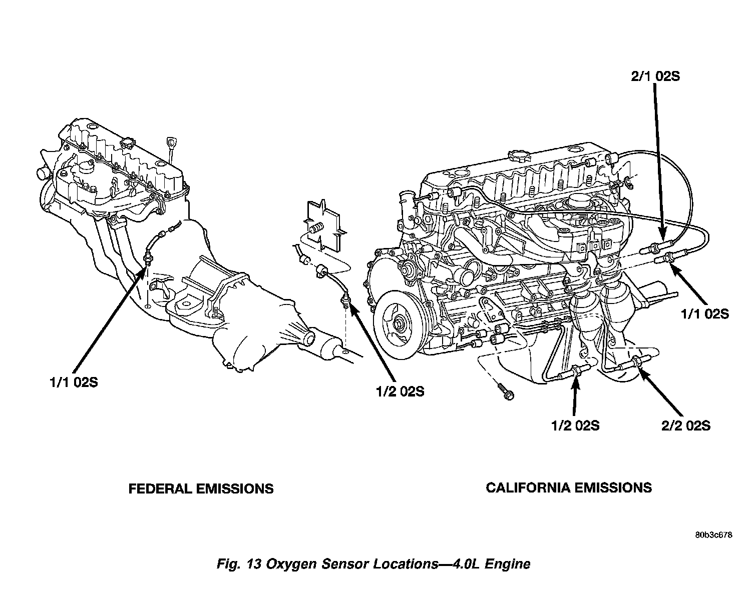
Fig. 14 Oxygen Sensor Locations - 4.7L V-8 Engine:
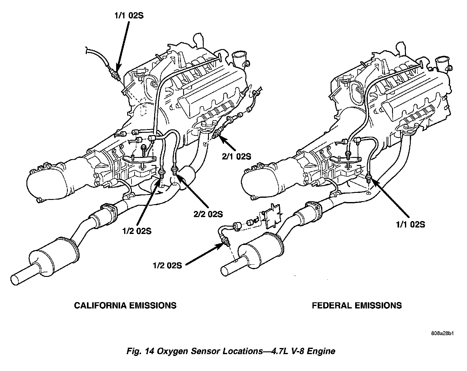
22. Verify all oxygen sensor wire connectors are firmly connected to sensors. Inspect sensors and connectors for damage (Fig. 13) or (Fig. 14).
23. Inspect for pinched or leaking fuel tubes/lines. Inspect for pinched, cracked or leaking fuel hoses.
24. Inspect for exhaust system restrictions such as pinched exhaust pipes, collapsed muffler or plugged catalytic convertor.
25. If equipped with automatic transmission, verify electrical harness is firmly connected to park/neutral switch and to transmission components.
Fig. 15 Fuel Filter/Fuel Pressure Regulator Location:
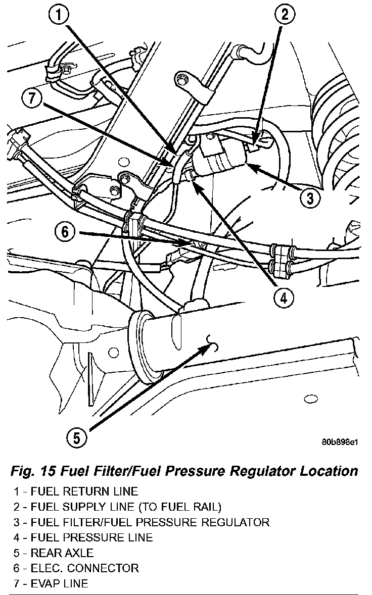
26. Verify fuel pump module pigtail harness electrical connector (Fig. 15) is firmly connected to body harness connector.
27. Inspect fuel line harness (from fuel pump module) at fuel filter/fuel pressure regulator (Fig. 15) for chaffing, cracks or leaks.
28. Verify battery cable and solenoid feed wire connections to starter solenoid are tight and clean.
29. Inspect for chaffed wires or wires rubbing up against other components.
30. Inspect for chaffed vacuum lines or lines rubbing up against other components.