Fuel Delivery and Air Induction: Description and Operation
FUEL DELIVERYThe fuel delivery system consists of:
- the fuel pump module containing the electric fuel pump, fuel gauge sending unit (fuel level sensor) and a separate fuel filter located at bottom of pump module
- a separate combination fuel filter/fuel pressure regulator
- fuel tubes/lines/hoses
- quick-connect fittings
- fuel injector rail
- fuel injectors
- fuel tank
- fuel tank filler/vent tube assembly
- fuel tank filler tube cap
- accelerator pedal
- throttle cable
The fuel tank assembly consists of: the fuel tank, fuel tank shield, fuel tank straps, fuel pump module assembly, fuel pump module locknut/gasket, and fuel tank check valve (refer to Emission Control System for fuel tank check valve information).
A fuel filler/vent tube assembly using a pressure/ vacuum, 1/4 turn fuel filler cap is used. The fuel filler tube contains a flap door located below the fuel fill cap.
Also to be considered part of the fuel system is the evaporation control system. This is designed to reduce the emission of fuel vapors into the atmosphere. The description and function of the Evaporative Control System is found in Emission Control Systems.
Both fuel filters (at bottom of fuel pump module and within fuel pressure regulator) are designed for extended service. They do not require normal scheduled maintenance. Filters should only be replaced if a diagnostic procedure indicates to do so.
Fig. 3 Fuel Filter/Fuel Pressure Regulator Location:
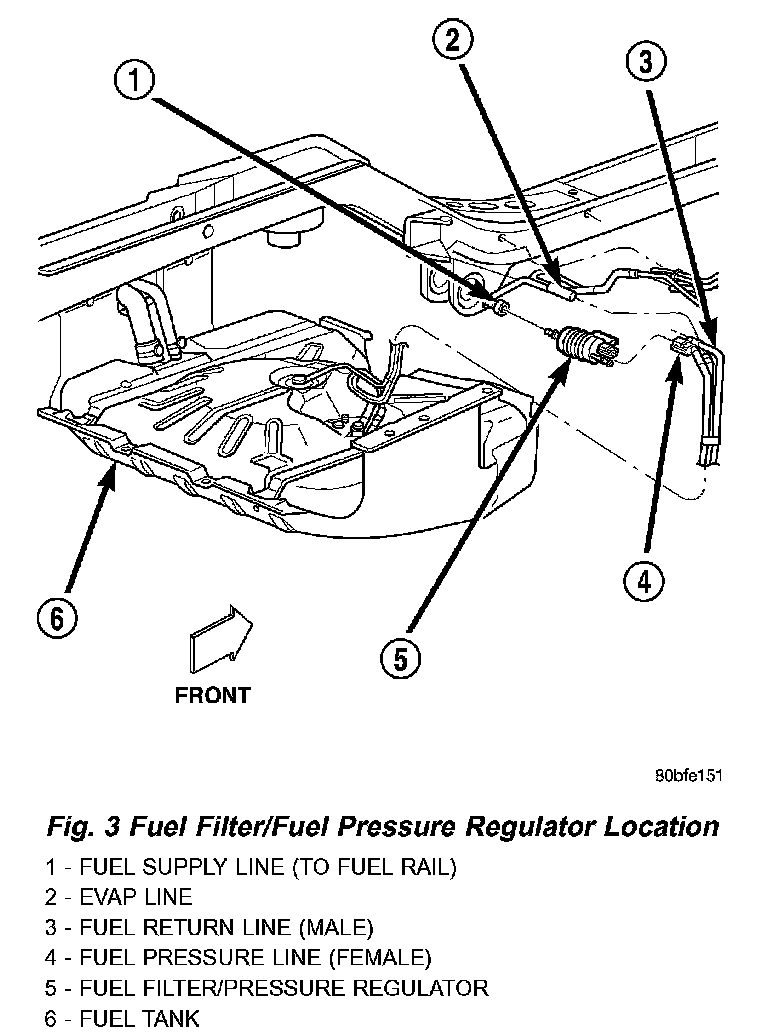
FUEL FILTER/PRESSURE REGULATOR
The combination fuel filter/pressure regulator is located in front of the fuel tank and above the rear axle (Fig. 3). It is transversely mounted to a chassis crossmember (left-to-right). Fuel Line Identification: The filter/regulator is equipped with 3 fuel line fittings (2 at one end and 1 at the other end). The single fitting facing the left side of the vehicle is the supply line to the fuel rail (Fig. 3). The 2 fittings facing the right side of the vehicle are connected to the fuel tank. Of these 2 fittings, the fitting towards the front is used for fuel return to the fuel tank. The fitting towards the rear is a pressure line.
Fuel Pressure Regulator Operation: The pressure regulator is a mechanical device that is not controlled by engine vacuum or the Powertrain Control Module (PCM).
The regulator is calibrated to maintain fuel system operating pressure of approximately 339 kPa ± 34 kPa (49.2 psi ± 5 psi) at the fuel injectors. It contains a diaphragm, calibrated springs and a fuel return valve. The internal fuel filter is also part of the assembly.
Fuel is supplied to the filter/regulator by the electric fuel pump. The regulator acts as a check valve to maintain some fuel pressure when the engine is not operating. This will help to start the engine. A second check valve is located at the outlet end of the electric fuel pump.
If fuel pressure at the pressure regulator exceeds approximately 49 psi, an internal diaphragm closes. Excess fuel is then routed into a separate fuel return line and returned to the fuel tank through the top of the fuel pump module.
Both fuel filters (at bottom of fuel pump module and within fuel pressure regulator) are designed for extended service. They do not require normal scheduled maintenance. Filters should only be replaced if a diagnostic procedure indicates to do so.
FUEL LEVEL SENDING UNIT / SENSOR
The fuel gauge sending unit (fuel level sensor) is attached to the side of the fuel pump module. The sending unit consists of a float, an arm, and a variable resistor track (card).
The fuel pump module has 4 different circuits (wires). Two of these circuits are used for the fuel gauge sending unit for fuel gauge operation, and for certain OBD II emission requirements. The other 2 wires are used for electric fuel pump operation.
For Fuel Gauge Operation: A constant input voltage source of about 12 volts (battery voltage) is supplied to the resistor track on the fuel gauge sending unit. This is fed directly from the Powertrain Control Module (PCM). NOTE: For diagnostic purposes, this 12V power source can only be verified with the circuit opened (fuel pump module electrical connector unplugged). With the connectors plugged, output voltages will vary from about 0.6 volts at FULL, to about 8.6 volts at EMPTY (about 8.6 volts at EMPTY for Jeep models, and about 7.0 volts at EMPTY for Dodge Truck models). The resistor track is used to vary the voltage (resistance) depending on fuel tank float level. As fuel level increases, the float and arm move up, which decreases voltage. As fuel level decreases, the float and arm move down, which increases voltage. The varied voltage signal is returned back to the PCM through the sensor return circuit.
Both of the electrical circuits between the fuel gauge sending unit and the PCM are hard-wired (not multi-plexed). After the voltage signal is sent from the resistor track, and back to the PCM, the PCM will interpret the resistance (voltage) data and send a message across the multi-plex bus circuits to the instrument panel cluster. Here it is translated into the appropriate fuel gauge level reading. Refer to Instrument Panel for additional information.
For OBD II Emission Monitor Requirements: The PCM will monitor the voltage output sent from the resistor track on the sending unit to indicate fuel level. The purpose of this feature is to prevent the OBD II system from recording/setting false misfire and fuel system monitor diagnostic trouble codes. The feature is activated if the fuel level in the tank is less than approximately 15 percent of its rated capacity. If equipped with a Leak Detection Pump (EVAP system monitor), this feature will also be activated if the fuel level in the tank is more than approximately 85 percent of its rated capacity.
FUEL LINES
Also refer to Quick-Connect Fittings.
WARNING: THE FUEL SYSTEM IS UNDER A CONSTANT PRESSURE (EVEN WITH THE ENGINE OFF). BEFORE SERVICING ANY FUEL SYSTEM HOSES, FITTINGS OR LINES, THE FUEL SYSTEM PRESSURE MUST BE RELEASED. REFER TO THE FUEL SYSTEM PRESSURE RELEASE PROCEDURE IN THIS GROUP.
The lines/tubes/hoses used on fuel injected vehicles are of a special construction. This is due to the higher fuel pressures and the possibility of contaminated fuel in this system. If it is necessary to replace these lines/tubes/hoses, only those marked EFM/EFI may be used.
If equipped: The hose clamps used to secure rubber hoses on fuel injected vehicles are of a special rolled edge construction. This construction is used to prevent the edge of the clamp from cutting into the hose. Only these rolled edge type clamps may be used in this system. All other types of clamps may cut into the hoses and cause high-pressure fuel leaks.
Use new original equipment type hose clamps.
FUEL PUMP
The electric fuel pump is located inside of the fuel pump module. A 12 volt, permanent magnet, electric motor powers the fuel pump. The electric fuel pump is not a separate, serviceable component.
Voltage to operate the electric pump is supplied through the fuel pump relay.
Fuel is drawn in through a filter at the bottom of the module and pushed through the electric motor gearset to the pump outlet.
Check Valve Operation: The pump outlet contains a one-way check valve to prevent fuel flow back into the tank and to maintain fuel supply line pressure (engine warm) when pump is not operational. It is also used to keep the fuel supply line full of gasoline when pump is not operational. After the vehicle has cooled down, fuel pressure may drop to 0 psi (cold fluid contracts), but liquid gasoline will remain in fuel supply line between the check valve and fuel injectors. Fuel pressure that has dropped to 0 psi on a cooled down vehicle (engine OFF) is a normal condition. Refer to the Fuel Pressure Leak Down Test for more information.
The electric fuel pump is not a separate, serviceable component.
Fig. 16 Fuel Tank And Components:
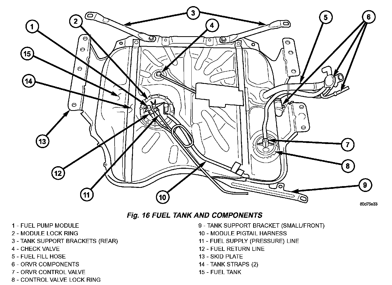
Fig. 17 Fuel Pump Module:
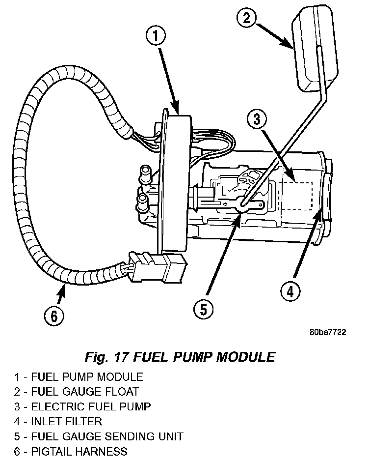
FUEL PUMP MODULE
The fuel pump module is installed in the top of the fuel tank (Fig. 16). The fuel pump module (Fig. 17) contains the following components:
- A separate fuel pick-up filter (strainer)
- An electric fuel pump
- A threaded locknut to retain module to tank
- A gasket between tank flange and module
- Fuel gauge sending unit (fuel level sensor)
- Fuel supply tube (line) connection
- Fuel return tube (line) connection
The fuel gauge sending unit and pick-up filter may be serviced separately. If the electrical fuel pump requires service, the entire fuel pump module must be replaced.
Refer to Fuel Pump, Fuel Filter/Fuel Pressure Regulator and Fuel Gauge Sending Unit.
FUEL RAIL
Fig. 20 Fuel Injector Rail - 4.7L V-8 Engine:
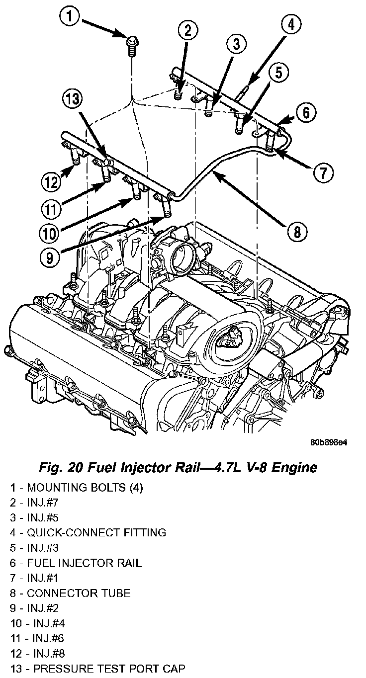
4.7L
The fuel injector rail is used to mount the fuel injectors to the engine. It is mounted to the intake manifold (Fig. 20).
High pressure fuel from the fuel pump is routed to the fuel rail. The fuel rail then supplies the necessary fuel to each individual fuel injector.
A fuel pressure test port is located on the fuel rail (Fig. 20). A quick-connect fitting with a safety latch is used to attach the fuel line to the fuel rail.
The fuel rail is not repairable.
Fig. 21 Fuel Injector Rail/Fuel Damper - 4.0L Engine:
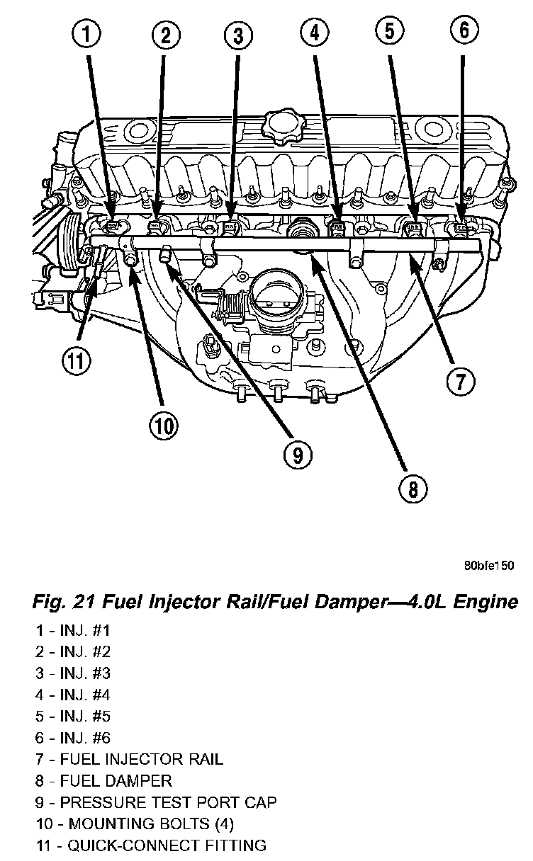
4.0L
The fuel injector rail is used to mount the fuel injectors to the engine (Fig. 21). On this engine, a fuel damper is located near the center of the fuel rail (Fig. 21).
The fuel injector rail supplies the necessary fuel to each individual fuel injector.
High pressure fuel from the fuel pump is routed to the fuel rail. The fuel rail then supplies the necessary fuel to each individual fuel injector.
The fuel damper is used only to help control fuel pressure pulsations. These pulsations are the result of the firing of the fuel injectors. It is not used as a fuel pressure regulator. The fuel pressure regulator is not mounted to the fuel rail on any engine. It is located near the front of the fuel tank above the rear axle. Refer to Fuel Filter/Fuel Pressure Regulator in this group for information.
A fuel pressure test port is located on the fuel rail (Fig. 21). A quick-connect fitting with a safety latch is used to attach the fuel line to the fuel rail.
The fuel rail is not repairable.
FUEL TANK
The fuel tank is constructed of a plastic material. Its main functions are for fuel storage and for placement of the fuel pump module and certain ORVR components.
All models pass a full 360 degree rollover test without fuel leakage. To accomplish this, fuel and vapor flow controls are required for all fuel tank connections.
A fuel tank check valve(s) is mounted into the top of the fuel tank (or pump module). Refer to Fuel Tank Check Valve for additional information.
An evaporation control system is connected to the check valve(s) to reduce emissions of fuel vapors into the atmosphere. When fuel evaporates from the fuel tank, vapors pass through vent hoses or tubes to a charcoal canister where they are temporarily held. When the engine is running, the vapors are drawn into the intake manifold. Certain models are also equipped with a self-diagnosing system using a Leak Detection Pump (LDP). Refer to Emission Control System for additional information.
Refer to ORVR for On-Board Refueling Vapor Recovery system information.
QUICK CONNECT FITTING
Different types of quick-connect fittings are used to attach various fuel system components, lines and tubes. These are: a single-tab type, a two-tab type or a plastic retainer ring type. Some are equipped with safety latch clips. Some may require the use of a special tool for disconnection and removal. Refer to Quick-Connect Fittings Removal/Installation for more information.
CAUTION: The interior components (O-rings, clips) of quick-connect fittings are not serviced separately, but new plastic spacers are available for some types. If service parts are not available, do not attempt to repair the damaged fitting or fuel line (tube). If repair is necessary, replace the complete fuel line (tube) assembly.