Turn Signal Flasher: Description and Operation
COMBINATION FLASHERCombination Flasher:
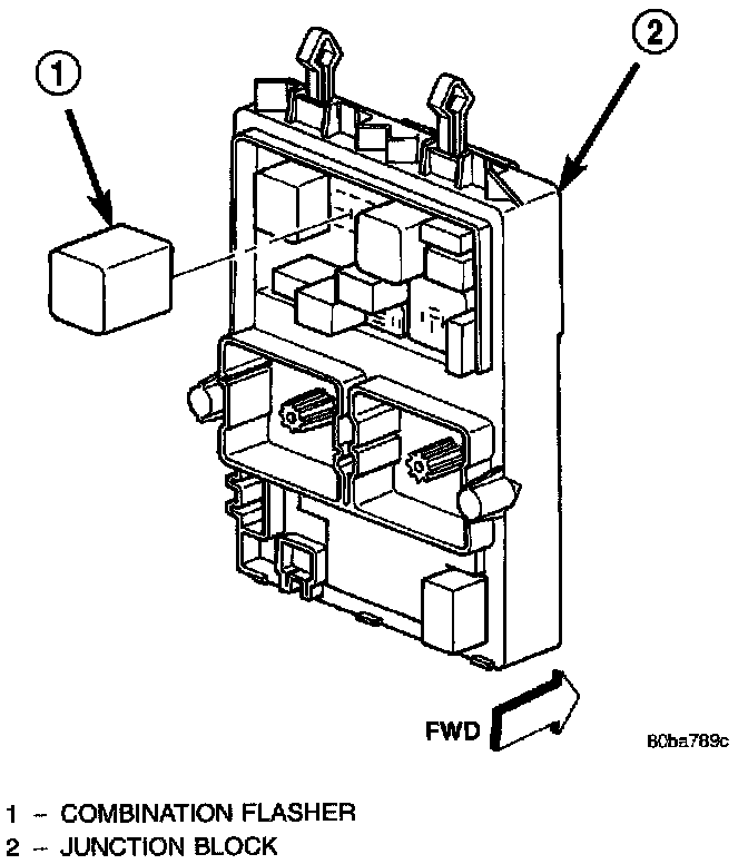
The combination flasher is located in the Junction Block (JB). The JB is located underneath the driver side of the instrument panel outboard of the steering column. The combination flasher is a smart relay that functions as both the turn signal system and the hazard warning system flasher. The combination flasher contains active electronic Integrated Circuitry (IC) elements. This flasher is designed to handle the current flow requirements of the factory-installed lighting. If supplemental lighting is added to the turn signal lamp circuits, such as when towing a trailer with lights, the combination flasher will automatically try to compensate to keep the flash rate the same.
The combination flasher has nine blade-type terminals that connect it to the vehicle electrical system. Refer to the appropriate wiring information.
Because of the active electronic elements within the combination flasher, it cannot be tested with conventional automotive electrical test equipment. If the combination flasher is believed to be faulty, test the turn signal system and hazard warning system circuits. (Refer to ELECTRICAL/LAMPS/LIGHTING - EXTERIOR - DIAGNOSIS AND TESTING - TURN SIGNAL & HAZARD WARNING SYSTEM). The combination flasher cannot be repaired or adjusted and, if faulty or damaged, it must be replaced.
The combination flasher controls the following inputs and outputs: B(+), fused ignition switch output, left turn switch sense, right turn switch sense, hazard switch sense, left front turn signal circuit, right front turn signal circuit, left rear turn signal circuit and right rear turn signal circuit. Constant battery voltage is supplied to the flasher so that it can perform the hazard warning function, and ignition switched battery voltage is supplied for the turn signal function. However, when the flasher is idle no current is drawn through the module. The unit does not become active until it is provided a signal ground from the turn signal switch, hazard warning switch or the Body Control Module (BCM).
Fig.7 Combination Flasher:
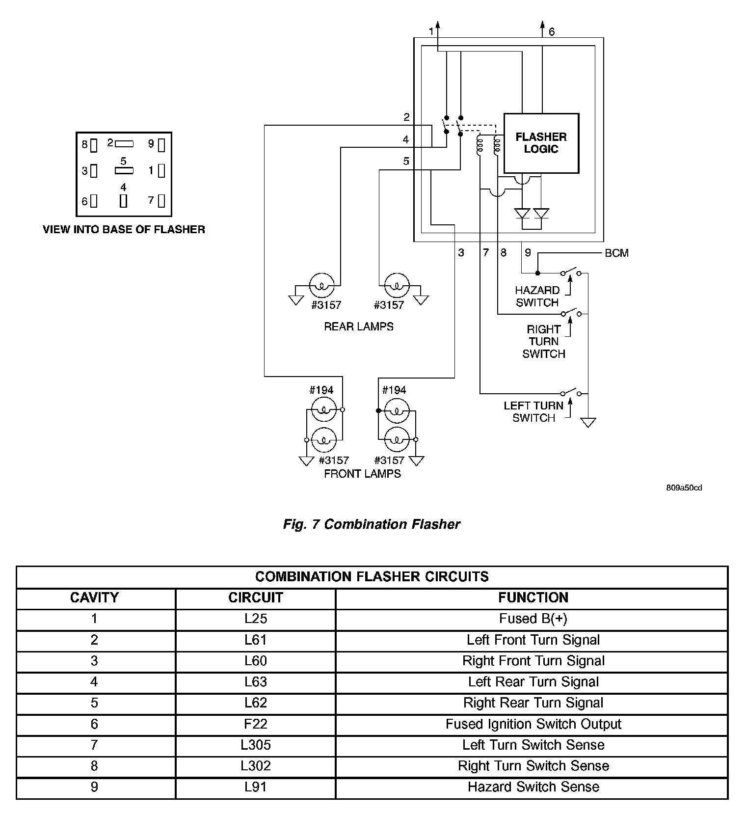
The IC within the combination flasher contains the logic that controls the flasher operation and the flash rate. When a bulb is burnt out, or when a circuit for a lamp is open, the turn signal flash rate will increase. However, an open lamp circuit or burnt out bulb does not change the hazard warning flash rate.
Turn signal inputs that actuate the combination flasher are low current grounds, each drawing a maximum of 300 milliamperes.The hazard warning signal input is a low current ground drawing a maximum of 600 milliamperes.