Hazard Warning Switch: Description and Operation
Fig.22 Left (Lighting) Multi-Function Switch:
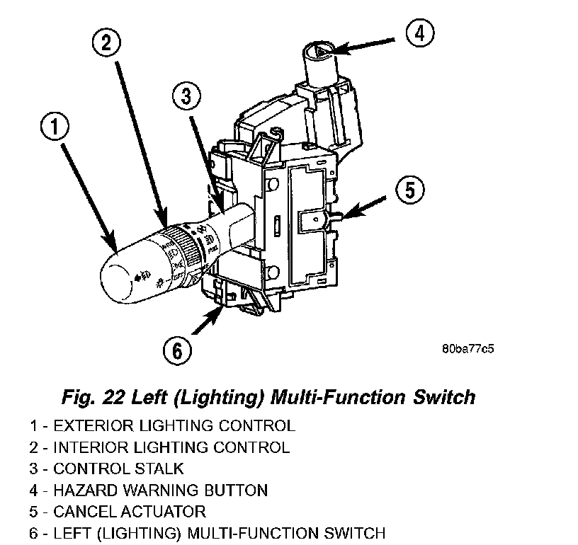
LEFT MULTI-FUNCTION SWITCH
The left multi-function switch, its mounting provisions, and its electrical connections are all concealed beneath the steering column shrouds, just below the steering wheel.
A single connector with eleven terminal pins is located on the back of the switch housing and connects the switch to the vehicle electrical system. The left multi-function switch supports the following exterior lighting functions:
- Auto Headlamps
- Front Fog Lamps
- Hazard Warning Control
- Headlamps
- Headlamp Beam Selection
- Headlamp Optical Horn
- Park Lamps
- Rear Fog Lamps
- Turn Signal Control
The left multi-function switch also supports the following interior lighting functions:
- Panel Lamps Dimming
- Interior Lamps Defeat
- Interior Lamps ON
- Parade Mode
The left multi-function switch cannot be adjusted or repaired. If any function of the switch is faulty, or if the switch is damaged, the entire switch unit must be replaced.
The left multi-function switch uses a combination of resistor multiplexed and conventionally switched outputs to control the many functions and features it provides using a minimal number of hard wired circuits. The switch is grounded to the chassis beneath the center floor console, just forward of the Airbag Control Module (ACM). Following are descriptions of the how the left multi-function switch operates to control the many exterior lighting functions and features it provides:
- Auto Headlamps - The automatic headlamps feature is provided by the Body Control Module (BCM), which monitors an input from a photodiode sensor located on the top of the instrument panel to detect ambient light levels whenever the ignition switch is in the ON position. Based upon the multiplexed input from the left multi-function switch and the input of the photodiode sensor, the BCM controls outputs to the park lamp and headlamp relays to illuminate or extinguish all exterior lighting.
- Front Fog Lamps - The Body Control Module (BCM) monitors the left multi-function switch then, based upon that switched ground input, controls an output to the front fog lamp relay to illuminate or extinguish the front fog lamps.
- Hazard Warning Control - The hazard warning push button is pressed down to activate the hazard warning system, and pressed down again to turn the system off. The left multi-function switch provides a ground to the hazard warning sense input of the combination flasher to control activation of the hazard warning lamps.
- Headlamps - The Body Control Module (BCM) monitors the left multi-function switch then, based upon that multiplexed input, controls an output to the headlamp low or high beam relays to illuminate or extinguish the headlamps.
- Headlamp Beam Selection - The Body Control Module (BCM) monitors the left multi-function switch then, based upon that switched ground input, controls an output to the headlamp low or high beam relays to activate the selected headlamp beam.
- Headlamp Optical Horn - The Body Control Module (BCM) monitors the left multi-function switch then, based upon that switched ground input, controls an output to the headlamp high beam relay to activate the headlamp high beams.
- Park Lamps - The Body Control Module (BCM) monitors the left multi-function switch then, based upon that multiplexed input, controls an output to the park lamp relay to illuminate or extinguish the parking lamps.
- Rear Fog Lamps - The Body Control Module (BCM) monitors the left multi-function switch then, based upon that multiplexed input, controls an output to the rear fog lamp relay to illuminate or extinguish the rear fog lamps.
- Turn Signal Control - The left multi-function switch control stalk actuates the turn signal switch. The Body Control Module (BCM) monitors the left multi-function switch then, based upon that multiplexed input, provides a variable voltage output to control the lighting of the turn signals.
Following are descriptions of the how the left multi-function switch operates to control the many interior lighting functions and features it provides:
- Panel Lamps Dimming - The Body Control Module (BCM) monitors the left multi-function switch then, based upon that multiplexed input, provides a variable voltage output through several panel lamps driver circuits to control the lighting of many incandescent panel lamps. The BCM also sends panel lamps dimming messages over the Programmable Communications Interface (PCI) data bus to other modules to control Display lighting levels in those modules.
- Interior Lamps Defeat - The Body Control Module (BCM) monitors the left multi-function switch then, based upon that multiplexed input, internally disables the function the BCM normally provides to control the illumination of the interior lamps.
- Interior Lamps ON - The Body Control Module (BCM) monitors the left multi-function switch then, based upon that multiplexed input, provides a control output to activate all of the interior lamp circuits.
- Parade Mode - The Body Control Module (BCM) monitors the left multi-function switch then, based upon that multiplexed input, provides a voltage output through several panel lamps driver circuits to control the lighting of many incandescent panel lamps. The BCM also sends panel lamps dimming messages over the Programmable Communications Interface (PCI) data bus to other modules on the bus to control lighting levels in those modules.