Part 1 of 3
LAMPS/LIGHTING - EXTERIORTurn Signal & Hazard Warning System
The turn signal and hazard warning system includes the following major components, which are described in further detail elsewhere in this service information:
- Combination Flasher
- Front Side Marker Lamps
- Hazard Warning Switch
- Turn Signal Cancel Cam
- Turn Signal Indicators
- Turn Signal Lamps
- Turn Signal Switch
The turn signal and hazard warning systems also provide the following features:
- Flash Lights with Lock - This customer programmable feature flashes the hazard warning lamps to provide optical verification that the Remote Keyless Entry (RKE) System has received a valid Lock or Unlock request from an RKE transmitter. (Refer to ELECTRICAL/POWER LOCKS - DESCRIPTION - REMOTE KEYLESS ENTRY SYSTEM).
- Panic Mode Optical Alert - This feature flashes the hazard warning lamps to provide an optical alert when the Remote Keyless Entry (RKE) System panic mode is activated by depressing the Panic button on an RKE transmitter. (Refer to ELECTRICAL/POWER LOCKS - DESCRIPTION - REMOTE KEYLESS ENTRY SYSTEM).
- Turn Signal ON Warning - This feature provides the vehicle operator with both visual and audible reminders when a turn signal has been left turned ON for an extended period. (Refer to ELECTRICAL/OVERHEAD CONSOLE/ELECTRONIC VEHICLE INFO CENTER - DESCRIPTION).
- Vehicle Theft Security System (VTSS) Optical Alarm - This feature flashes the hazard warning lamps to provide an optical alarm when the VTSS is armed and activated by an unauthorized entry into the vehicle. (Refer to ELECTRICAL/VEHICLE THEFT SECURITY - DESCRIPTION - VEHICLE THEFT SECURITY SYSTEM).
The turn signal system operates on battery current received on a fused ignition switch output (RUN) circuit so that the turn signals will only operate with the ignition switch in the ON position. The hazard warning system operates on non-switched battery current received on a fused B(+) circuit so that the hazard warning remains operational regardless of the ignition switch position. When the turn signal system is activated, the circuitry of the turn signal switch and the combination flasher will cause the selected (right or left) turn signal indicator, front park/turn signal lamp, front side marker lamp and rear tail/stop/turn signal lamp to flash ON and OFF. When the hazard warning system is activated, the circuitry of the hazard warning switch and the combination flasher will cause both the right side and the left side turn signal indicators, front park/turn signal lamps, front side marker lamps and rear tail/ stop/turn signal lamps to flash ON and OFF.
The Body Control Module (BCM) can also activate the hazard warning system lamps by energizing the combination flasher through a single hard wired connection to the hazard warning switch sense circuit. The BCM grounds the circuit to energize and de-energize the combination flasher in response to message inputs received over the Programmable Communications Interface (PCI) data bus network. The BCM can energize the combination flasher when the VTSS is requested.
Vehicles equipped with the optional Electronic Vehicle Information Center (EVIC) use turn signal status messages received from the Electro-Mechanical Instrument Cluster (EMIC) and distance messages received from the Powertrain Control Module (PCM) over the PCI data bus to determine when the Turn Signal ON warning should be activated. The EMIC receives hard wired inputs from the combination flasher to operate the turn signal indicators, then sends the proper turn signal status message to the EVIC. If a turn signal is left on for more than about 1.6 kilometers (1 mile) of driving distance, the EVIC will display a visual "Turn Signal ON" message and will send a request to the BCM over the PCI data bus to notify the vehicle operator.
During both the turn signal and the hazard warning operation, if the exterior lamps are turned OFF, the front park/turn signal lamps and the front side marker lamps will flash in unison. If the exterior lamps are turned ON, the front park/turn signal lamps and the front side marker lamps will flash alternately Refer to the owner's manual.
Exterior Lighting Battery Saver
The BCM monitors the status of and controls the park lamp, head lamp and fog lamp relay's. If any exterior lamps are left ON after the ignition is turned OFF, the BCM will turn them OFF after 8 minutes.
BRAKE LAMP SWITCH
The brake lamp switch is mounted on a bracket attached to the brake pedal support The switch is adjustable.
The brake lamp switch is used for the brake lamp, speed control and brake sensor circuits.
COMBINATION FLASHER
Combination Flasher:
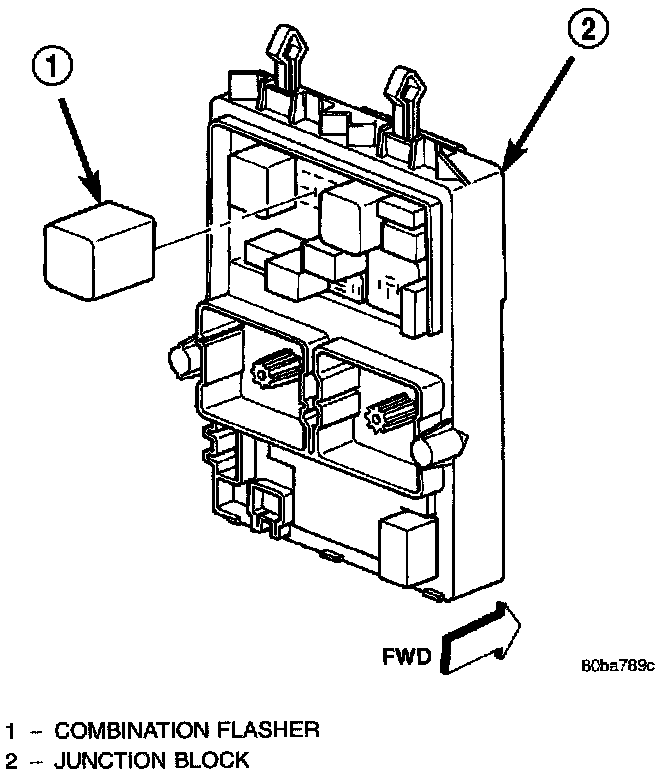
The combination flasher is located in the Junction Block (JB). The JB is located underneath the driver side of the instrument panel outboard of the steering column. The combination flasher is a smart relay that functions as both the turn signal system and the hazard warning system flasher. The combination flasher contains active electronic Integrated Circuitry (IC) elements. This flasher is designed to handle the current flow requirements of the factory-installed lighting. If supplemental lighting is added to the turn signal lamp circuits, such as when towing a trailer with lights, the combination flasher will automatically try to compensate to keep the flash rate the same.
The combination flasher has nine blade-type terminals that connect it to the vehicle electrical system. Refer to the appropriate wiring information.
Because of the active electronic elements within the combination flasher, it cannot be tested with conventional automotive electrical test equipment. If the combination flasher is believed to be faulty, test the turn signal system and hazard warning system circuits. (Refer to ELECTRICAL/LAMPS/LIGHTING - EXTERIOR - DIAGNOSIS AND TESTING - TURN SIGNAL & HAZARD WARNING SYSTEM). The combination flasher cannot be repaired or adjusted and, if faulty or damaged, it must be replaced.
The combination flasher controls the following inputs and outputs: B(+), fused ignition switch output, left turn switch sense, right turn switch sense, hazard switch sense, left front turn signal circuit, right front turn signal circuit, left rear turn signal circuit and right rear turn signal circuit. Constant battery voltage is supplied to the flasher so that it can perform the hazard warning function, and ignition switched battery voltage is supplied for the turn signal function. However, when the flasher is idle no current is drawn through the module. The unit does not become active until it is provided a signal ground from the turn signal switch, hazard warning switch or the Body Control Module (BCM).
Fig.7 Combination Flasher:
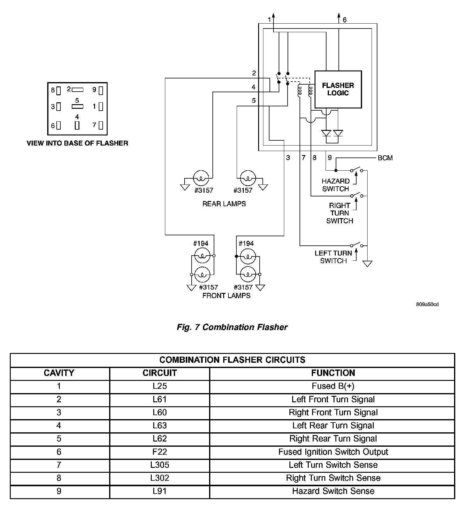
The IC within the combination flasher contains the logic that controls the flasher operation and the flash rate. When a bulb is burnt out, or when a circuit for a lamp is open, the turn signal flash rate will increase. However, an open lamp circuit or burnt out bulb does not change the hazard warning flash rate.
Turn signal inputs that actuate the combination flasher are low current grounds, each drawing a maximum of 300 milliamperes.The hazard warning signal input is a low current ground drawing a maximum of 600 milliamperes.
DAYTIME RUNNING LAMP MODULE
The Daytime Running Lights (Headlamps) System is installed on vehicles manufactured for sale in Canada only A separate module, mounted in the junction block under the dash, controls the DRL.
The headlamps are illuminated at a reduced intensity when the engine is running, headlamp switch OFF and the parking brake released.
HEADLAMP
The headlamps are modular in design. The headlamp module contains five bulbs; a dual filament headlamp low beam bulb, a single filament high beam bulb, two turnsignal/park bulbs, and a side marker bulb.
All headlamp, turnsignal, park lamp, and high beam operations are controlled by the left multifunction switch. Exterior lamps and bulbs are serviceable separately.